......
Is that going to work? It's a single primary (no issues) but the output is drawn as a single secondary with multiple taps... how will it act with one set connected backwards?
I'm asking out of ignorance...
is it winding primary side of secondary side - that's matter of choice
however , answer on your particular question is impossible without having exact xformer for test
anyway , as written several times - F6 xformer is classic repeater , with windings formed (in factory ,by convention) as 150+150:150+150
there are many specimens as that , being 4 windings of 150R , or just two center tapped 600R and any possible mix of these two
(150R being matter of convention ; load it differently , check frequency , and world is your oyster)
if any xformer at hand is having windings on hand to achieve needed connection for F6 , that's it ....... under condition that it covers entire freq. spectrum as needed
Last edited:
Just finished a F6, on one of the amp channels the LED is not lighting. It is installed in the correct polarity.
The two boards of the pair are not the same, and I seem to recall that one of the LED silk screen patterns could be wrong,
but at any rate use your DVM to trace out the connections for the led.
I will check tomorrow.
Also, I made a schoolboy error and had the PSU +/- leads installed backwards on the amp board in that channel for a few seconds before I noticed the lightbulb not dimming and LEDS on PSU not lighting (as happened on the other mono channel). Embarrassing I know. I managed to set bias and dc after that, just the LED which is not lighting up. Have I potentially fried anything ??
Also, I made a schoolboy error and had the PSU +/- leads installed backwards on the amp board in that channel for a few seconds before I noticed the lightbulb not dimming and LEDS on PSU not lighting (as happened on the other mono channel). Embarrassing I know. I managed to set bias and dc after that, just the LED which is not lighting up. Have I potentially fried anything ??
it can be either resistor (value) or LED
replace all zillion of them , and it will be repaired
I forgot to write - keep rotating them , 'till it works

F6 bias voltage 2v5 and 23v0 ??
Hi,
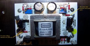
I built up the white converter pcbs of teabags with all resistors, caps, pots, input jfets, one blue led & the transformer, output SSJFets not installed.
So, I powered up and leds light up, PS volts +-23V.
Check the voltage between ground and R7, and pot P1 varies volts from 0v0 and 2v5.
Check the voltage between ground and R8, and pot P2 varies volts from 20v9 and 23v0 ???
Any ideas?
Also, am I correct that what I will need to bias the SSJFets is 1v2?
Hi,
I built up the white converter pcbs of teabags with all resistors, caps, pots, input jfets, one blue led & the transformer, output SSJFets not installed.
So, I powered up and leds light up, PS volts +-23V.
Check the voltage between ground and R7, and pot P1 varies volts from 0v0 and 2v5.
Check the voltage between ground and R8, and pot P2 varies volts from 20v9 and 23v0 ???
Any ideas?
Also, am I correct that what I will need to bias the SSJFets is 1v2?
Attachments
it seems you forgot "minus" somewhere
and you also forgot to put reference to schematic , hopefully one with SS outputs .......
and you also forgot to put reference to schematic , hopefully one with SS outputs .......
read, please .
when we are talking of your amp , it is necessary that one with thinking cap is you , not someone else
lower bias is properly measured between neg PSU rail and pot wiper (if you needlessly measure it ref. to gnd , voltage is neg (minus) just because black DVM probe is black with reason)
upper bias voltage is measured between gnd and pot wiper
read, please .
when we are talking of your amp , it is necessary that one with thinking cap is you , not someone else
lower bias is properly measured between neg PSU rail and pot wiper (if you needlessly measure it ref. to gnd , voltage is neg (minus) just because black DVM probe is black with reason)
upper bias voltage is measured between gnd and pot wiper
OK, that works better. 😉 Thanks.
19.3V across R13 on working channel and 3mV across R13 in non-working
Ok, 3mV/15k gives 3/15 uA, which probably is due to your meter loading alone. Measure the R13 resistance, it could be open.
If R13 is ok, the LED could be backwards, or it was damaged from the reverse supply voltage. Replace the LED,
making certain with your DVM that the cathode end connects to ground. I seem to remember it being mentioned that the silk
is wrong, so check it.
Last edited:
When I install the Led I am usually too lazy to check the orientation and do it from memory and my success rate is around 50%, it's just to see that the circuit is on not bias. If it was bias I would be more careful. I turn the same Led around if it does not work and it has always worked. Tough little buggers from my experience with them.
Confirmed it is the wrong way around, I took another LED and just touched the terminals on R13 and GND in reverse polarity and it lit up. I have biased it up and music playing so looks like no damage from the temporary miswiring of + and -, thank god. 😱
When I install the Led I am usually too lazy to check the orientation and do it from memory and my success rate is around 50%, it's just to see that the circuit is on not bias. If it was bias I would be more careful. I turn the same Led around if it does not work and it has always worked. Tough little buggers from my experience with them.
Yup. Probability will usually give you 50%. (If you miss more than 50% on a true-false test, one should flip a coin.) Usually there is a resistor associated with it, and many times if you hold the board up to a light you can see a trace from the resistor the to positive LED hole.
Russellc
Yup. Probability will usually give you 50%. (If you miss more than 50% on a true-false test, one should flip a coin.) Usually there is a resistor associated with it, and many times if you hold the board up to a light you can see a trace from the resistor the to positive LED hole.
Russellc
But Murphy's law comes into play, maybe less than 50%. It is a simple easy fix so I do not fret on it too much. I have started checking the orientation more of late before installing.
Day 3 with the new F6. Last night I noticed a low level hum/noise coming from the right speaker, only really noticeable when putting my ear up against the tweeter and woofer - wasn't bothersome. Last night I left the amp on overnight for the first time to get things to break in a bit. This morning I am getting significant noise on that same right channel. It is even noticeable while playing music. The left channel is dead quiet.
I powered down the amp for 30min, and when powering back up it is still there.
What are some potential causes of this and things I can check with the DMM to try to isolate the problem?
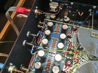
I have attached an image of the grounding scheme as this might help. What is odd is that the left channel is dead quiet and L and R are wired the same. The middle GND of both PSU boards are connected in 4 separate locations.
I powered down the amp for 30min, and when powering back up it is still there.
What are some potential causes of this and things I can check with the DMM to try to isolate the problem?
I have attached an image of the grounding scheme as this might help. What is odd is that the left channel is dead quiet and L and R are wired the same. The middle GND of both PSU boards are connected in 4 separate locations.
Attachments
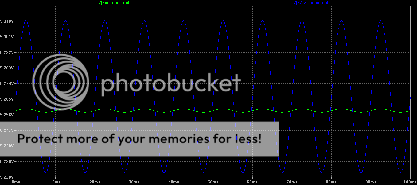
Here is the difference in regulation between 9.1V Zener and Zen Mod's 6.2V Zener circuit.
It's possible you might be experience this issue, your speakers are quite sensitive.
Get rid of the 9.1V Zener.
It's possible you might be experience this issue, your speakers are quite sensitive.
Get rid of the 9.1V Zener.
Last edited:
Any chance you have connected different source equipment to the amp?
same source, I have only 1
- Home
- Amplifiers
- Pass Labs
- F6 Illustrated Build Guide