I've got signal coming off the secondary of the JT123 transformer before R11 going into Q1, but not before R12 going into Q2.
I expected signal at both locations, but I have the same behavior on the good channel.
Signal is coming from the JFETS Q4/Q4 Sources, so that's good.
I expected signal at both locations, but I have the same behavior on the good channel.
Signal is coming from the JFETS Q4/Q4 Sources, so that's good.
Was a silpad. Replaced with ceramic and thermal paste, which I've used on my other builds with fine thermal success.what's mosfet thermal interface arrangement?
if you had silpads for prolonged time, quite possible that mosfets had tough (thermal) history, so once you can expect them misbehaving
so, if you're sure that zener voltage is stable, no other suspects than mosfets
so, if you're sure that zener voltage is stable, no other suspects than mosfets
I suppose I'm in luck that I have some extra IRFP240 mosfets around. At least I think I do.
I'm confident about the zeners, but will pull the board and triple check there isn't something else with a bad solder / loose connection. Just did a ten minute from cold, current climb to 440mV and hold, with a 1k signal and both good and bad channel were measuring the same output into a dummy 8 ohm load, and then suddenly bad channel started dropping in current and voltage output to about half of the good channel. It climbs and then seems to reach a cliff and gives up.
For my education, why wasn't I able to see signal at the gate of the V-- side's MOSFET? My understanding is the Jensen transformer is inverting the signal for the "underbelly" and then both MOSFETS are recreating the same output in the old Dr. Doolittle Push-Me-Pull-Me.
to measure signal at secondaries, you need to put probes across each secondary ends ........... but considering how "big" that signal is, you need scope for that, and that scope must be floating (ref. to GND)
so, facts:
-if you can confirm proper Rdc of each secondary,
-if you have signal to speakers (same in both channels) up to the point of wakoo,
... there is no reason to doubt anything in front of mosfets, meaning both JFet input buffer and xformer are doing their job
so, if zener voltage(s) is(are) unchanged, what else than mosfet?
I am once again enjoying the sonic stylings of my F6.
Thanks again for the help, Zen.
Thanks again for the help, Zen.


Finished this F6 recently; my first DIY amp. Reading schematics and holding a soldering iron are familiar things for me, but there's no doubt in my mind this project succeeded on the first try only due to the wealth of knowledge shared here!
Deluxe 4U case, PSU boards, amplifier boards with transformers and transistors all sourced from the store. Antek 150VA power transformers. Filter caps from Apex Jr and most everything else from Mouser. I built this amp stock save for the picomods and dual mono power supplies. Currently biased at 550mv. I found nothing tricky at all to implement the dual mono configuration; each PSU drives its own channel with each PSU board grounded through its own CL60 to the single star ground. This power supply configuration allows short wiring runs but due to my stacked PSU getting to the bias adjustments is tricky. I left the wires to all panels long so I may remove any heatsink or panel without disconnecting any wiring. Final biasing had the case stacked together like a house of cards; only bolting it together once that was complete 😛 Absolutely zero hum with no extra shielding on input transformer or twisted wiring needed. Build it as described by 6L6 and it will be dead quiet. Entire build was straightforward with no surprises save some trepidation during biasing until the meters started showing activity (I started with all pots at their middle range). Once I started getting readings I found everything to be quite linear and the absolute final adjustments were made after cooking it for an hour between each adjustment.
Layout of transformers and rectifier bridges. The transformer on right does not yet have all its wires dressed; finished state will be as the left side. You can see the all thread standoffs in place that will support the PSU boards above the transformers. Heatsinks and amplifier boards only mocked up here; heat shrink is still in place to protect from scratches.

All PSU wiring completed and being tested. PSU boards mounted in place to standoffs using riser panels from the store. I wished to mount the PSU boards using the holes between the filer caps and therefore could not use a simple standoff as the transformers would be in the way. The riser panels mount to the all thread standoffs, and the PSU boards than mount to the riser with wiring from the rectifiers coming up through the the middle. Notice that the riser panels are notched to clear the caps on the amp boards and how access to the bias and offset pots is not convenient. Wiring of IEC terminal and power transformers is as all other Firstwatt amps with two CL60 to limit inrush and a safety cap across the line voltage. Difficult to make out in the picture but the standoffs nearest the line voltage terminal block each have pieces of neoprene tubing slid over them as extra insurance against abrading the power wires.

Completed wiring. You can make out the CL60 for ground on each PSU board. The green wire from each heads to the star ground where the IEC ground and transformer static shields are also connected. Shielded coax for signal inputs; it and the line voltage input wiring again left long so the back panel can be unbolted and laid flat if desired.

Initial biasing in progress before stacking the case together to "cook" for an hour. Final setting was 550mV with 0V offset.

How I was able to easily mount the front panel. Notice nut driver with extension and allen bit attached. This made what would have been a tedious operation a breeze by zipping all four screws right in! Also a good shot of final wiring. Coiled twisted pair goes to LED indicator in face plate. Also a good shot showing notches in riser panel to clear caps on amp board.

Time to solder the input coax to the amp boards and close up rear panel.

Good overall internal shot. There's about 1/4" clearance between the filter caps and top cover when fitted.

Big sexy beast at just over 40 pounds! Handles are rose gold kitchen cabinet pieces from Amazon. LED displays are holes drilled through front panel and then filled with hot glue. LED's are then hot glued onto back of faceplate so glue acts as a diffusor. Only thing I will change at this point is to up the resistance to the display LED's as I find this too bright. I may add an additional power switch to the front panel in the future but at same time I tend to leave my amps on 24 hrs a day so not a necessity.

Gratuitous amp porn shot 😍

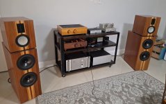
This amp has floored me! It drives a pair of DIY Jim Holtz/Curt Campbell Bordeaux speakers and I was concerned I'd be lacking power as this amp replaces a PAIR of Carvers that were each bridged to over 200W as monoblocks. My speakers are setup to accommodate bi-amping and if the F6 lacked grunt the back up plan was to run it through the mids and ribbons only and leave the bass to something else. I was gobsmacked when I first installed the F6! I can only describe it as fantastic sounding and cannot believe how deep the bass goes and how well controlled it is. The midrange and ribbons are also signing like they never have and these speakers now show me what they are truly capable of. This "little" amp beats the crap out of what was there before and can take on all comers; regardless of power. After adjusting speaker levels in my processor I can still push the volume to uncomfortable levels if desired with absolutely zero noise. This project has exceeded my expectations in every way thanks to all who've shared along the way. Enjoy the music!
Deluxe 4U case, PSU boards, amplifier boards with transformers and transistors all sourced from the store. Antek 150VA power transformers. Filter caps from Apex Jr and most everything else from Mouser. I built this amp stock save for the picomods and dual mono power supplies. Currently biased at 550mv. I found nothing tricky at all to implement the dual mono configuration; each PSU drives its own channel with each PSU board grounded through its own CL60 to the single star ground. This power supply configuration allows short wiring runs but due to my stacked PSU getting to the bias adjustments is tricky. I left the wires to all panels long so I may remove any heatsink or panel without disconnecting any wiring. Final biasing had the case stacked together like a house of cards; only bolting it together once that was complete 😛 Absolutely zero hum with no extra shielding on input transformer or twisted wiring needed. Build it as described by 6L6 and it will be dead quiet. Entire build was straightforward with no surprises save some trepidation during biasing until the meters started showing activity (I started with all pots at their middle range). Once I started getting readings I found everything to be quite linear and the absolute final adjustments were made after cooking it for an hour between each adjustment.
Layout of transformers and rectifier bridges. The transformer on right does not yet have all its wires dressed; finished state will be as the left side. You can see the all thread standoffs in place that will support the PSU boards above the transformers. Heatsinks and amplifier boards only mocked up here; heat shrink is still in place to protect from scratches.
All PSU wiring completed and being tested. PSU boards mounted in place to standoffs using riser panels from the store. I wished to mount the PSU boards using the holes between the filer caps and therefore could not use a simple standoff as the transformers would be in the way. The riser panels mount to the all thread standoffs, and the PSU boards than mount to the riser with wiring from the rectifiers coming up through the the middle. Notice that the riser panels are notched to clear the caps on the amp boards and how access to the bias and offset pots is not convenient. Wiring of IEC terminal and power transformers is as all other Firstwatt amps with two CL60 to limit inrush and a safety cap across the line voltage. Difficult to make out in the picture but the standoffs nearest the line voltage terminal block each have pieces of neoprene tubing slid over them as extra insurance against abrading the power wires.
Completed wiring. You can make out the CL60 for ground on each PSU board. The green wire from each heads to the star ground where the IEC ground and transformer static shields are also connected. Shielded coax for signal inputs; it and the line voltage input wiring again left long so the back panel can be unbolted and laid flat if desired.
Initial biasing in progress before stacking the case together to "cook" for an hour. Final setting was 550mV with 0V offset.
How I was able to easily mount the front panel. Notice nut driver with extension and allen bit attached. This made what would have been a tedious operation a breeze by zipping all four screws right in! Also a good shot of final wiring. Coiled twisted pair goes to LED indicator in face plate. Also a good shot showing notches in riser panel to clear caps on amp board.
Time to solder the input coax to the amp boards and close up rear panel.
Good overall internal shot. There's about 1/4" clearance between the filter caps and top cover when fitted.
Big sexy beast at just over 40 pounds! Handles are rose gold kitchen cabinet pieces from Amazon. LED displays are holes drilled through front panel and then filled with hot glue. LED's are then hot glued onto back of faceplate so glue acts as a diffusor. Only thing I will change at this point is to up the resistance to the display LED's as I find this too bright. I may add an additional power switch to the front panel in the future but at same time I tend to leave my amps on 24 hrs a day so not a necessity.
Gratuitous amp porn shot 😍
This amp has floored me! It drives a pair of DIY Jim Holtz/Curt Campbell Bordeaux speakers and I was concerned I'd be lacking power as this amp replaces a PAIR of Carvers that were each bridged to over 200W as monoblocks. My speakers are setup to accommodate bi-amping and if the F6 lacked grunt the back up plan was to run it through the mids and ribbons only and leave the bass to something else. I was gobsmacked when I first installed the F6! I can only describe it as fantastic sounding and cannot believe how deep the bass goes and how well controlled it is. The midrange and ribbons are also signing like they never have and these speakers now show me what they are truly capable of. This "little" amp beats the crap out of what was there before and can take on all comers; regardless of power. After adjusting speaker levels in my processor I can still push the volume to uncomfortable levels if desired with absolutely zero noise. This project has exceeded my expectations in every way thanks to all who've shared along the way. Enjoy the music!
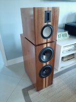
Okay... So I reread your post Damon. Did you say that you have the Bordeaux speakers? Post a pic! I would like to see them! Attached are a couple of pictures of a pair that I built. One of the pics has a F6 I built too. There are a couple of things about the F6 that seem to help with the Bordeaux. They go into class AB a bit and they double their wattage at 4 ohms. I believe the Bordeaux are a 6 ohm load. I built mine with a single power supply and 400va transformer. I built out the diode section of the power supply board which may have helped a bit with the AB performance characteristics. I assume your massive power supply has that part covered. I could shake the pictures on the wall with that amp.
The Bordeaux are great speakers. They really respond to the room due to their rear firing mid and tweeter design so speaker placement and room treatment are fun to play with. Also, with the level of detail that they have, you really get to hear the differences between amps.
I like them as far out as possible from the front wall, wide apart and toed in about 15 degrees off axis from the listening position. This seems to get a really nice balance of soundstage and imaging. It seems to set the center image back quite a ways. Also, having the center clear of your equipment so the mid top can do their work seems to help too (the attached picture is an old one)
Maybe the next time you make a parts order you can pick this up?
https://www.digikey.com/en/products/detail/bourns-inc/3296X-1-502LF/1088078
Side adjustment vs top so you can face it up towards the top of the amp and shorten your wires if you like. Double-check the specs.
Attachments
Okay... So I reread your post Damon. Did you say that you have the Bordeaux speakers? Post a pic! ... ... ...
Maybe the next time you make a parts order you can pick this up?
https://www.digikey.com/en/products/detail/bourns-inc/3296X-1-502LF/1088078
Side adjustment vs top so you can face it up towards the top of the amp and shorten your wires if you like. Double-check the specs.
Excellent idea on the right angle pot! I didn't know there was such a thing!
I've built many speakers over the years but the Bordeaux continue to do it for me. These are supplemented with a 15" Ultimax in a sealed cab driven by a Crown amp via miniDSP. Once I installed the F6 I had to start from scratch on integrating the sub once again! I run the Bordeaux full range with no high pass and the sub low pass is 40hz. I wanted a single piece tower so the cabs are taller in the woofer area to enclose the proper volume. My speakers stand on feet with the large flared port out the bottom. Port dimensions, baffle width, driver spacing, midrange tunnel length and woofer volume is per the plans. Like you I find them best toed in slightly.
Front baffles have a 2" radius on vertical edges. The screws provide clamping during glue up; they were then removed and holes filled. These radius pieces are prefabricated parts often used by cabinet builders and are available in many different sizes. They do complicate the rest of the structure as the inside of the front baffle is no longer a simple square corner.
Before back went on. Chamber at far right remains open for backside of tweeter; midrange tunnel will also be open at back. Large opening at far left is for the flared port. Braided teflon CAT5 cable for internal wiring. After backs went on cabinets were veneered and driver recesses and holes routed before adding xovers and damping material. All cabinet structure is 3/4" MDF.
Backs veneered first so the sides and top can cover the veneer edges. All openings here remain open. Filled spots cover brads used during assembly.
Stained and ready for clear poly, xover and driver installation.
Poor lighting but shows shape of baffle to good effect.
4 cubic foot sub is down firing and stands on aluminum furniture legs. As a joke to myself in not being able to make anything square I built this in a diamond shape. As I thought about it more I realized I could use this shape to make the sub appear visually smaller since front side will not be perpendicular to the viewer. For corner placement this illusion truly works! Previously I had a "plain" cube 4 cubic foot sub and everyone will fight you insisting this one is smaller. It's not!
Sub being built up. I detest laminated speaker baffles as I find them structurally inefficient and wasteful. Far more rigidity to be gained with well thought out bracing (and it's lighter!). Internal bracing behind baffle receives the mounting screws from sub and feeds those forces into horizontal window braces and cabinet sides. Baffle is effectively now a truss; far more rigid structure than a "dumb" laminated panel. Recessed baffle hides down firing sub from view. Furniture legs will bolt into the corners of baffle. Again all 3/4" MDF.
Entire front stage. Center channel is the Statements Center built exactly to plans. Amps on floor drove each main until F6 took over!
Very cool. Thank you for sharing in such great detail. I suspect the laminated baffles are more for the screws to bite into due to the sub drivers being recessed into the baffle. Still, your truss idea takes care of that problem. Those cabinet roundovers are pretty neat.
Enjoy the F6! It is a great amp. I used a BA2018 pre and a B1 Korg Pre with it. Both are terrific. That would be a great next project.
Enjoy the F6! It is a great amp. I used a BA2018 pre and a B1 Korg Pre with it. Both are terrific. That would be a great next project.
Down the road will be a turntable and phono preamp as the wife wants some vinyl!Very cool. Thank you for sharing in such great detail. I suspect the laminated baffles are more for the screws to bite into due to the sub drivers being recessed into the baffle. Still, your truss idea takes care of that problem. Those cabinet roundovers are pretty neat.
Enjoy the F6! It is a great amp. I used a BA2018 pre and a B1 Korg Pre with it. Both are terrific. That would be a great next project.
Hi folks,
Got some trouble building F4 in Deluxe 4U Iron chassis. PSU works properly, got +25V and -25V (depending on mains voltage), difference between + and - is minor, 0,02V variation - I suppose a good result. After firing up with light bulb on Live (no short) - right channel got LED bright. No smoke, proceeded with normal IEC cord (no bulb). After ~2h temperature was stabilized and readings were pretty stable. I managed to set BIAS to 600 mV (+- 10 mV fluctuations), 0.0 mV Offset (+- 0.5mV). 45 degr C on heat sink, ~55 C on Jfets.
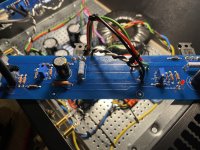
After connecting left channel to the PSU (with bulb) - no short, no smoke but also LED doesn't glow. Checked several times polarity of the LED - was good (+ towards R13), LED itself is working - checked several times after desoldering. Started to measure voltages. +17 on "+V" (all measurements were taken with bulb on Live, so lower than should be). OK here. +17V on R7 - OK as well. Minus 17V on R13... has to be +17V... Not good. Can't find any bridges on the board. PSU wires connected properly (see image below). As there was no smoke, checked if I can set bias and offset. Can increase bias, tried 90mV with bulb. Can regulate DC offset. Tried it for ~5-10 mins, no smoke. Took some readings on output transistors (with a bulb on Live):
Q1:
Source: 0V;
Drain: +17V;
Gate: +3,79V.
Q2:
Source: -17V;
Drain: -0.06V;
Gate: -13,29V.
My knowledge of electronics is VERY basic, so I have no idea if those readings are ok, please advise.
Another observation. On working channel (right) - amp is turned off - there is 0 Ohm between R13 and +V (as it should). Between R13 and -V, resistance is growing from 5 to 30 Ohms quite quickly and goes up. On the problematic channel with no LED light (left) - it is opposite: 0 Ohm between -V and R13 (it is not good as far as I understand), growing resistance between +V and R13, where should be no resistance.
Was afraid to test it with normal mains cord (no bulb). Green -V; Red +V, White - speakers out; Black - PSU and Speaker GND.
Kindly ask you guys to help me with that. Thank you in advance.
Regards,
Nicholas
Got some trouble building F4 in Deluxe 4U Iron chassis. PSU works properly, got +25V and -25V (depending on mains voltage), difference between + and - is minor, 0,02V variation - I suppose a good result. After firing up with light bulb on Live (no short) - right channel got LED bright. No smoke, proceeded with normal IEC cord (no bulb). After ~2h temperature was stabilized and readings were pretty stable. I managed to set BIAS to 600 mV (+- 10 mV fluctuations), 0.0 mV Offset (+- 0.5mV). 45 degr C on heat sink, ~55 C on Jfets.
After connecting left channel to the PSU (with bulb) - no short, no smoke but also LED doesn't glow. Checked several times polarity of the LED - was good (+ towards R13), LED itself is working - checked several times after desoldering. Started to measure voltages. +17 on "+V" (all measurements were taken with bulb on Live, so lower than should be). OK here. +17V on R7 - OK as well. Minus 17V on R13... has to be +17V... Not good. Can't find any bridges on the board. PSU wires connected properly (see image below). As there was no smoke, checked if I can set bias and offset. Can increase bias, tried 90mV with bulb. Can regulate DC offset. Tried it for ~5-10 mins, no smoke. Took some readings on output transistors (with a bulb on Live):
Q1:
Source: 0V;
Drain: +17V;
Gate: +3,79V.
Q2:
Source: -17V;
Drain: -0.06V;
Gate: -13,29V.
My knowledge of electronics is VERY basic, so I have no idea if those readings are ok, please advise.
Another observation. On working channel (right) - amp is turned off - there is 0 Ohm between R13 and +V (as it should). Between R13 and -V, resistance is growing from 5 to 30 Ohms quite quickly and goes up. On the problematic channel with no LED light (left) - it is opposite: 0 Ohm between -V and R13 (it is not good as far as I understand), growing resistance between +V and R13, where should be no resistance.
Was afraid to test it with normal mains cord (no bulb). Green -V; Red +V, White - speakers out; Black - PSU and Speaker GND.
Kindly ask you guys to help me with that. Thank you in advance.
Regards,
Nicholas
Attachments

Nicholas,
On one of the PCBs, the LED is actually on the negative rail instead of the positive (ie, it doesn't match the schematics). Unfortunately I don't remember which one it is. But since your R13 is attached to the V- then that is the problem. Simply turn the LED around and continue.
Dennis
On one of the PCBs, the LED is actually on the negative rail instead of the positive (ie, it doesn't match the schematics). Unfortunately I don't remember which one it is. But since your R13 is attached to the V- then that is the problem. Simply turn the LED around and continue.
Dennis
Last edited:
Dennis,Nicholas,
On one of the PCBs, the LED is actually on the negative rail instead of the positive (ie, it doesn't match the schematics). Unfortunately I don't remember which one it is. But since your R13 is attached to the V- then that is the problem. Simply turn the LED around and continue.
Dennis
Thanks for the reply. Turning LED is not a problem at all considering that I spent 2 evenings on finding the reason why I got minus on R13 instead of plus, as should be according to the schematic. Are you sure that on one PCB LED is on the negative rail? I got one LED on positive on working PCB, so the “defective” PCB has to have LED on minus, according to you.
Thanks,
Nicholas
- Home
- Amplifiers
- Pass Labs
- F6 Illustrated Build Guide