The wattage rating of the F5 can be doubled by increasing the voltage of the power supply from 24v to 32v. Can this also be done with the F6? Would this fry the jfet gain stage? Would the heat sinking of the 5U chassis be adequate? Answers to these questions would be greatly appreciated.
Many answers to questions like these in the thread....
Russellc
When you say Jfet. I am assuming you mean the input jfets.
I designed a high power version, JPS did the pcb for it.
He might have some pcbs left.
Are there Gerber's published for this board, and does it use same output as your "special recipe" or something else?
I have now another set of Jensons to repopulate my F6 boards. I also pirated the input jfets, so will replace them.
Seems like I remember they needed ( or preferred ) lower idss?
As long as I am ordering stuff, what rails will this monster use?
Many thanks,
Russellc
Last edited:
I changed to IRFP250/IXTH64N10L2 R4-22ohm.
Sounding nice and warm.
Thank you for great mod pico.
I will try IRFP140 tomorrow.
Sounding nice and warm.
Thank you for great mod pico.
I will try IRFP140 tomorrow.
Another one comes to life 🙂
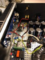
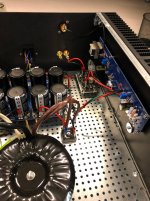
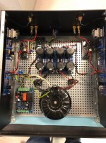
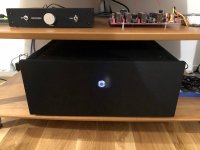
Built with 6.0 V Zener and R7/8 = 3k32, R11/12 = 110R and IRFP150 in the output.
In a 4U 400 chassis.
Mark Johnsons softstart and XRK DC protection in the output.
It sounds absolutely wonderful paired with the B1 Korg - it has been playing for 1 and half week and it is just... wow...
A few photos are attached 😀
Attachments
Are there Gerber's published for this board, and does it use same output as your "special recipe" or something else?
I have now another set of Jensons to repopulate my F6 boards. I also pirated the input jfets, so will replace them.
Seems like I remember they needed ( or preferred ) lower idss?
As long as I am ordering stuff, what rails will this monster use?
Many thanks,
Russellc
JPS will have the gerbers
Output devices can be whatever you want but IXTH64N10L2 is particularly good in terms of power dissipation.
Idss will depend on rails but 8mA will likely be ok. The part is cascoded at input to lower dissipation.
You could do rails as high as 50V if you wanted, but 35V to 40V would be a little more sensible.
Last edited:

Using Green LEDs with higher voltage drop...
2 picoDumbs,
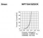
Looks like there are "Pure Green" LEDs with 3.2V voltage drop?
https://sg.element14.com/cree/c503b-gcn-cy0c0791/led-green-t-1-3-4-5mm-12-5cd-535nm/dp/1855512
If that is the case, I can do with 2x of these vs 3x of standard Green LEDs with 2.1V forward voltage? I ask because the Tea-Bag boards have space on the PCB for 2 LEDs; of course a third unit can be accommodated by DIY.
Any experience with these Green LEDs with 3.2V forward voltage?
Anything over 5.5V should be adequate to bias up the mosfets.
You can change the resistor values - anything between 3mA and 8mA will be certainly functional.
You will get better performance with higher currents though eg 7mA.
You will see I recommend using 3 green leds but you could also use 3 red leds
2 picoDumbs,
Looks like there are "Pure Green" LEDs with 3.2V voltage drop?
https://sg.element14.com/cree/c503b-gcn-cy0c0791/led-green-t-1-3-4-5mm-12-5cd-535nm/dp/1855512
If that is the case, I can do with 2x of these vs 3x of standard Green LEDs with 2.1V forward voltage? I ask because the Tea-Bag boards have space on the PCB for 2 LEDs; of course a third unit can be accommodated by DIY.
Any experience with these Green LEDs with 3.2V forward voltage?
Last edited:
Nice, that’s beautiful work. I’m excited to start my build. I am in the middle of building a pair of full range speakers, which will be completed in another week or so.
2 picoDumbs,
Looks like there are "Pure Green" LEDs with 3.2V voltage drop?
https://sg.element14.com/cree/c503b-gcn-cy0c0791/led-green-t-1-3-4-5mm-12-5cd-535nm/dp/1855512
If that is the case, I can do with 2x of these vs 3x of standard Green LEDs with 2.1V forward voltage? I ask because the Tea-Bag boards have space on the PCB for 2 LEDs; of course a third unit can be accommodated by DIY.
Any experience with these Green LEDs with 3.2V forward voltage?
Looks like 3.2 V at 20mA.
Check the data sheet for 5 mA to 8 mA operation.
I have never used them so can't comment.
The ones I recommended are guaranteed to be extremely low noise.
Last edited:
Pico,
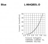
Thanks for the guidance. Even with the Blue LEDs I have in place, looks like I am having less than 3.2V drop as I am operating at lower MA.
Let me check if I can find a similar graph for Green LEDs.
p.s. Found the datasheet for a suitable green model - this actually shows steeper drop with increasing mA, so possibly better choice in this application.
Attachments
Last edited:
The ones I recommended are guaranteed to be extremely low noise.
Missed this one earlier - not sure if you have recommended any specific type of LEDs. If not, would welcome your inputs.
Good night or good morning! 😀
Well, as luck would have it, I have 18 of the same Green LEDs that Pico mentions in Post # 1 of that thread... 🙂
So I just bought the F6 kit from the DIYAudio Store. So do I build it as is or do I make any changes to the components or wiring? It seems that there have been quite a few modifications to build over time.
I am building 2- PS in a separate enclosure with the DIYAudio PS Boards with 60K in capacitance. I was thinking about using a 400VA with 2x20VAC secondaries. I will be using the PS box for powering one clone amp channel normally, but occasionally using it to power two. I bi-amp my speakers. Will I have any issues with any of the Pass clone amps with this PS arrangement, such as lack of capacitance?
I don't have room for all the pass clone amps and want to experience them all so will just build all the amp boards on heat sinks and swap them out as heat sink and amp boards. Making my own 4U 330mm x 300mm mini-dissipante out of modushop parts and some other fabricated materials.
So I just bought the F6 kit from the DIYAudio Store. So do I build it as is or do I make any changes to the components or wiring? It seems that there have been quite a few modifications to build over time.
led mod is worthwhile
- Home
- Amplifiers
- Pass Labs
- F6 Illustrated Build Guide