I use a soldered connection with 12 awg wire between the psu 0V and the board.
The PSU 0V is connected to chassis earth via a thermistor.
Just look at 6L6s build guide.
Some people do different star earth arrangements but I haven't needed to do any of that.
It's up to you.
The PSU 0V is connected to chassis earth via a thermistor.
Just look at 6L6s build guide.
Some people do different star earth arrangements but I haven't needed to do any of that.
It's up to you.
Out of curiosity, what sort of connectors are you using for DC between PSU and amp?
I think I will be using an XLR connector. Probably a 4 or 5 pin version so I don't inadvertently plug in a 3 pin XLR.
That probably will not have the current capacity you need. A Neutrix PowerCon would work fine. It is pulling a few amps continuously fro the PSU.I think I will be using an XLR connector. Probably a 4 or 5 pin version so I don't inadvertently plug in a 3 pin XLR.
Also putting some of the PSU capacitors in the amp box would be good, that will help alleviate the issues of the separate chassis with the extra power cable's inductance and resistance etc.
Neutrik strongly advised me not to use the powercon connectors for DC, as they are not designed for DC.
They suggested for DC applications to use these:
NC4MXX-B | Neutrik
Each pin is good for 10A DC.
That may or may not be adequate depending on your application.
They suggested for DC applications to use these:
NC4MXX-B | Neutrik
Each pin is good for 10A DC.
That may or may not be adequate depending on your application.
Out of curiosity, what sort of connectors are you using for DC between PSU and amp?
no connectors between PSU and amp , because the shorter and the lesser is always the better 😉
.
For internal use.
The only connectors I would use on a powersupply would be xt60 or ec3 connectors.
Some people use spades but one of these inline connectors is much better.
The only connectors I would use on a powersupply would be xt60 or ec3 connectors.
Some people use spades but one of these inline connectors is much better.

The cl60, I think you have to connect it to the middle 2 pins of the connector, and remove the other one, if input power is 240v. For 120v, you need to parallel the windings, and the cl60 in series.
Last edited:
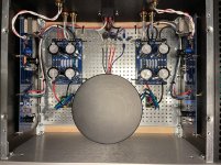
@bbm3 - Hang on! I rarely chime in with my lack of knowledge, but I assume you've checked your PSU voltages. If not, do that before changing anything. The wiring specifically related to the CL-60s and primaries looks OK to me based on a standard dual primary Antek transformer and 120VAC mains, but I may have missed something. Looks like your CL-60s are wired between the two hot and two neutral per the schematic for 120VAC mains. That doesn't rule out everything, but again, I assume you checked your PSU. If you have, then move on, if not stop and wait if you're not 100% sure of what to do next based on mine and previous comments.
---------------
If you've checked your PSU.
I don't know of a reference schematic with expected voltages / currents.
I don't see any stuffing errors on the amp boards, but some areas are not clear in the pics, and my eyesight is not wonderful.
Have you turned P2? Did you intentionally turn P2 all the way or partially one direction before installation b/c of the notes in the build guide that bias may be too high at P2 mid-point?
I'd wait for others to chime in, but if my PSU was working properly, and if I had checked my amp boards for obvious stuffing errors and used a DBT to check for shorts; I would turn P2 until Q2 turns on indicated by seeing voltage across R2. I'd start with clockwise. If I didn't see it turn on when I turned P2 in one direction, then I'd turn it the other. If the pot went to max turns in both directions without any current (or not enough) through R2, I'd report back. Depending on the level of success, zeners and/or values for for R11, R12 may come up.
Note - I am a novice, but that's what I'd do. I'm not in the FAB club yet, and I may have it wrong, but I think it's low risk. Lower risk is waiting for a more experienced member or moderator to chime in and say that I'm a dodo and lay out a more clear path. 😀
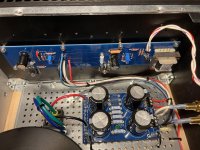
Thank you for the feedback. I did indeed mis-wire the CL60. I did check everything from the wall to the power supply outputs one stage at a time before energizing the next.
Everything is working correctly now.
Thanks for everyone”s help.
Everything is working correctly now.
Thanks for everyone”s help.
Last edited:
Fantastic! Sorry if that alarmed you. So, what was wrong on the PSU side? The CL-60s looked correct in the picture, but clearly I missed something. What did I miss? Were you not getting a negative rail?
It did work the way I had it but the CL-60 was only limiting one input. I tied Both red leads together and both black leads together and removed the CL-60 on the neutral side much neater and how it should have been.
The real problem is I had to turn P2 way more than I expected in order to begin seeing voltage across R2. Now I have P2 turned to the limit and I am only seeing 2.45V. I will move on to offset and watch what happens to the bias.
The real problem is I had to turn P2 way more than I expected in order to begin seeing voltage across R2. Now I have P2 turned to the limit and I am only seeing 2.45V. I will move on to offset and watch what happens to the bias.
Thanks for that! Truly appreciated. I love to learn from these threads.
#1 doesn't track with me, but that's clearly due to my lack of knowledge. I'll ponder, observe, study the schematics again, and hopefully learn.
#2 tracks completely with my limited understanding and was what I was alluding to re: potentially not enough current through R2 => Bias at Q2 => Maybe Zener / R11 / R12 adjustment depending on your particular results. Again... just noodling. One thing I've learned is that if I post something completely ignorant, a number of helpful people will jump in to correct it. 🙂
Either way, I'm happy that it seems to be going according to plan. Sorry if I derailed progress. 🙂
Last edited:
No apology!
I”m totally new to this too. Well at least using a linear power supply.
I built a pair of Amp Camps, a couple B1’s and some simple chip amps but this has many new challenges for me.. Thanks for looking over my shoulder as we learn together..
I’ll keep you posted if you like.
Thanks again for the help.
-Bill
- Home
- Amplifiers
- Pass Labs
- F6 Illustrated Build Guide