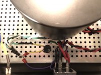
Do you have an AS series antek transformer with electrostatic shield and shield wire (purple)?
If yes, this wire is connected directly to chassis not to ground lift side of thermistor. I would use a ring connector and connect it directly to the bolted chassis earth wire.
Hope that makes sense.
If yes, this wire is connected directly to chassis not to ground lift side of thermistor. I would use a ring connector and connect it directly to the bolted chassis earth wire.
Hope that makes sense.
Thanks for all the help so far!!!!!
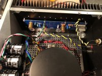
In this photo, you don't have the electrostatic screen connected direct to chassis earth.
It's not connected at all.
That's bloody terrible.
Hahahaha
You have something weird going on.
apparently! 😀
hard to see from picture - IEC mid pin ( safety GND) must go directly to chassis, under one screw
then connect everything else , NTC from audio GND included , to same screw
lately boys elected that sole NTC isn't safe enough for purpose, so resorted to diode bridge+NTC+cap ( search for details) as more safe solution
and yes- orientation of NTC is irrelevant, same as any other resistor
The safety earth wire (from the iec connector) should be connected directly to the chassis on the other side of the thermistor, but it looks like you might have it connected on the ground lift side of thermistor.
If so this is wrong.
I have pulled this thing apart many times now trying to isolate the issue, so some of my pictures show ground wires where you wouldn't want them for normal operation.
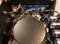
Now I have everything back to the way it should be - IEC ground to chassis along with the purple lead of the toroidal and one leg of the thermistor all bolted together to the chassis using ring terminals. The other leg of the thermistor goes to PSU ground and that is the only place the PSU board is grounded to the chassis.
That's bloody terrible.
Hahahaha
You have something weird going on.
I removed the amp from the PSU and measured the same thing on the + and - rails of the PSU. DC is 25v/-25v and I see a blip of 0.020 AC every few seconds on either rail. So it seems I have isolated whatever is happening to the PSU.
I also checked the DC side of the bridge rectifiers without the PSU hooked up and found 18v DC and 5.9v AC. Should I expect to see AC on the DC side?
I also checked the DC side of the bridge rectifiers without the PSU hooked up and found 18v DC and 5.9v AC. Should I expect to see AC on the DC side?
That is most likely the AC ripple on the dc, but I would need to see it on a scope to be certain.
I don't think I would be alarmed to see that.
I removed the amp from the PSU and measured the same thing on the + and - rails of the PSU. DC is 25v/-25v and I see a blip of 0.020 AC every few seconds on either rail. So it seems I have isolated whatever is happening to the PSU.
1) Bad/Loose conections somewhere - poorly crimped faston connectors, poorly bolted ground conections etc.
2) Cold solder joints
3) Bad capacitor
4) DC on the mains
5) Bad bridge rectifier
6) Bad cable - internally fractured
7) Grounding issue
8) Hum pickup on the Jensen.
That is everything I can think of, not in any particular order.
Try eliminating each possibility, start with the easiest ones.
Last edited:
I removed the amp from the PSU and measured the same thing on the + and - rails of the PSU. DC is 25v/-25v and I see a blip of 0.020 AC every few seconds on either rail. So it seems I have isolated whatever is happening to the PSU.
Could be dc on the mains, loose/bad connections or cables, bad capacitor/s, bad bridge rectifier/s.
To be realistic, you need to check your power supply rails including the caps with a load on them that'll be about 16R to produce a 1.5A current, or 8R for the both channel current on each rail- and see if the transformer 'growls' with this load.
The other thing is to consider the centre ground links you've added on the power supply pcb as your central audio ground and run your speaker return, the input shield, and the amplifier board ground to this single point - from this, the wire that goes to your 'ground lift' thermistor (+ bits later) means that central point on your power supply will have 7 wires to it - that's why you might consider using a house mains copper/brass earth strip as they have about 10 screw down points on them.
There's a diagram on the M2 build that clearly shows this.
At present, you have a string of ground wires, particularly with the speaker return going back to the amp pcb instead of directly to the power supply.
This isn't universal by any means - you can see photos of factory First watt amplifiers and they've connected the speaker return to the amp boards but this is worth a try as it seems you have a 'built-in' problem somewhere.
Anyway, suggest you try this ...
Aha, found it!
An externally hosted image should be here but it was not working when we last tested it.
even if you're not too keen on the idea.It seems the 'link thing' hasn't worked - it's called
"M2 STAR Earth Layout Wiring scheme Mud Map2.jpg"
"M2 STAR Earth Layout Wiring scheme Mud Map2.jpg"
That will most likely be a better way, although I don't bother with this and have better than 50uV at the output.
I suspect there is something far more dumb at play here - ie he has a serious problem, usually something dumb.
That's worth trying out though.
It's possible that in the process of doing that he might discover the original issue.
I suspect there is something far more dumb at play here - ie he has a serious problem, usually something dumb.
That's worth trying out though.
It's possible that in the process of doing that he might discover the original issue.
Last edited:
I remember "FullRange" up in Brisbane had some trouble with 'hum' when he upgraded his F5 to F6.
I found the photo of how he reorganized the ground wires on a bus-bar between the return speaker terminals - it's on the thread "Upgrade F5 to F6" and it's post #168 on march 29/2016 - 'way back then. you could also do it as 'dual mono' with another CL-60 maybe ...
And yes, I think Glen has just missed something somewhere that keeps getting overlooked - I can't think of what it might be hence the idea of concentrating the ground wires
Sometimes these sorts of things appear in TVA's and can 'drive you nuts'! I'm playing around with the idea of combining Dave Slagles TVA with Uriah Daley's Clone-Note boards to avoid the problematic online selector switch and that's guaranteed to produce some headaches! (probably simpler to get one if those fancy expensive rotary switches)
Nice sunshine for the middle of winter, eh!
It is pulsating DC at 120Hz when there are no caps connected. So measure with meter on DC setting. 18V DC is correct. When the caps are connected, they will charge to the top value 1.4*18I also checked the DC side of the bridge rectifiers without the PSU hooked up and found 18v DC and 5.9v AC. Should I expect to see AC on the DC side?
I discovered that my Fluke DVM actually blips from 0vac to 0.020vac at idle without anything connected to it, so the hum measurement across the binding posts with speakers attached was not valid. I need to replace my Fluke.
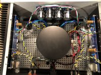
I ended up finishing my amp and it’s back together, sounding great and in a much better state than when I first completed it. I like this configuration with the PSU screwed to the face plate. That resulted in a much cleaner wiring job than when it was mounted on the chassis floor. I also like the toroid cover. The cover gives the amp a professional look.
And so with having gone over my soldering again, twisting wires and checking parts, I can still hear a faint hum with my ear pressed to the speakers, but from 6’ away I can’t hear it at all. Next step is to get an electrician to look into my house wiring for issues.
Thanks for all your help!!!
Attachments
I discovered that my Fluke DVM actually blips from 0vac to 0.020vac at idle without anything connected to it, so the hum measurement across the binding posts with speakers attached was not valid. I need to replace my Fluke.
I’ll suggest that you need to replace the battery in the Fluke, not the meter itself...
That's bloody terrible.
Hahahaha
You have something weird going on.
I’ll suggest that you need to replace the battery in the Fluke, not the meter itself...
Thanks, that was the first thing I tried. Unfortunately the Fluke still behaved badly.
If you write an email to fluke they may repair it or replace it for free if it wasn't too old.
It's worth enquiring about.
It's worth enquiring about.
If you write an email to fluke they may repair it or replace it for free if it wasn't too old.
It's worth enquiring about.
Thanks - I am definitely going to follow up with them -
Fluke Tech Support 1-800-443-5853
With the test wires shorted?Thanks, that was the first thing I tried. Unfortunately the Fluke still behaved badly.
- Home
- Amplifiers
- Pass Labs
- F6 Illustrated Build Guide