Any chance it is a preamp problem?
Have you tried driving the "bad" amp channel from the opposite preamp channel?
Have you tried driving the "bad" amp channel from the opposite preamp channel?
Check the solder joints on the transformer, and everywhere else.
It's likely you have a cold solder joint somewhere that is thermally affected.
It's likely you have a cold solder joint somewhere that is thermally affected.
LED Bias and Noise, noise, noise...
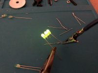
I completed the zenner change to LEDs and replaced R7, R8 with 3R3k ohm resistors. This is a nice change as the bias adjustment is a lot less sensitive and a lot more accurate than with the 6.2v zenner/10k ohm combination. DC offset is easier to zero out as well. I am still fiddling with those adjustments on both amps but I’m close to calling it a day on these settings.
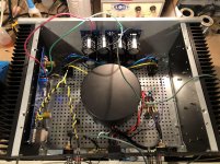
As for my hum, it is still present and accounted for at a very low level in the speakers. I have done a lot of work trying to get rid of the hum in my speakers but so far nothing has worked. I soldered and re-soldered parts and added more ground ties across the boards on the PSU. I moved the toroid to the chassis and added a cover. I moved the PSU board to the back of the fascia plate. I swapped out wires. I grounded the PSU directly to the chassis bypassing the CL-60 to try that temporarily. Nothing is working.
The hum starts about a minute or two after the amp turns on and never changes in pitch or intensity no matter what I do. I think I’m at the last resort which is to build up a new PSU board hoping that maybe I have a bad cap on my existing board.
Anyway, aside from this incredibly annoying issue that can only be heard with ones ear pressed right next to a speaker cone, the amp does sound good-to-great. Imaging, soundstage and detail are all excellent with the SBA-761s I built earlier this summer. I’m going to put it all back together so I can listen to it while I build up another PSU.
Thanks for all the help so far!!!!!
I completed the zenner change to LEDs and replaced R7, R8 with 3R3k ohm resistors. This is a nice change as the bias adjustment is a lot less sensitive and a lot more accurate than with the 6.2v zenner/10k ohm combination. DC offset is easier to zero out as well. I am still fiddling with those adjustments on both amps but I’m close to calling it a day on these settings.
As for my hum, it is still present and accounted for at a very low level in the speakers. I have done a lot of work trying to get rid of the hum in my speakers but so far nothing has worked. I soldered and re-soldered parts and added more ground ties across the boards on the PSU. I moved the toroid to the chassis and added a cover. I moved the PSU board to the back of the fascia plate. I swapped out wires. I grounded the PSU directly to the chassis bypassing the CL-60 to try that temporarily. Nothing is working.
The hum starts about a minute or two after the amp turns on and never changes in pitch or intensity no matter what I do. I think I’m at the last resort which is to build up a new PSU board hoping that maybe I have a bad cap on my existing board.
Anyway, aside from this incredibly annoying issue that can only be heard with ones ear pressed right next to a speaker cone, the amp does sound good-to-great. Imaging, soundstage and detail are all excellent with the SBA-761s I built earlier this summer. I’m going to put it all back together so I can listen to it while I build up another PSU.
Thanks for all the help so far!!!!!
Attachments
Last edited:
@glenv6: Can you measure the hum? The commercial First Watt version has a noise spec of 200uV. My build measures about 175uV.
What speakers do you have again?
It could be a cold solder joint on the psu.
Try measuring the temperature of each capacitor after the amp has been on for an hour.
Maybe also measure how much dc offset there is at the source pins of the jfets.
So this hum definitely occurs with the amp connected to the speakers but nothing else connected to the amp?
Either twist the red/black and green power cables together or use zip ties to tie them together, or replace red, black, green wires with 14awg 3 core cable.
This might not fix the specific problem but this should be done out of good wiring practice.
This might not fix the specific problem but this should be done out of good wiring practice.
Last edited:
@glenv6: Can you measure the hum? The commercial First Watt version has a noise spec of 200uV. My build measures about 175uV.
Interesting - How would I measure the hum? I have a Fluke 115 DVM, but I don't have an oscilloscope, unfortunately.
Interesting - How would I measure the hum? I have a Fluke 115 DVM, but I don't have an oscilloscope, unfortunately.
You only have to measure to determine if you have something very bad/unusual or not.
A fluke multimeter will easily tell you that.
You should easily be able to measure 500uV.
If it is 1mV AC then you have a problem that certainly shouldn't be there.
If it's less than 500uV then most likely your speakers are just super sensitive, in which case build a better power supply.
Last edited:
What speakers do you have again?
My mains are SBA-761s designed by Troels Gravesen that i built earlier this summer. The issue happens with any speakers I plug into it. I'm using Advent Mini indoor/outdoor speakers on my bench, plus a variety of junkie old raw drivers of various impedances.
It could be a cold solder joint on the psu.
Try measuring the temperature of each capacitor after the amp has been on for an hour.
I went over those solder joints, but I will check the temp of each capacitor.
Maybe also measure how much dc offset there is at the source pins of the jfets.
Would that be one probe on the source pin and the other to ground?
So this hum definitely occurs with the amp connected to the speakers but nothing else connected to the amp?
Yes. And it has never varied on either amp. That's why I'm thinking that it could be a cap in the PSU. Someone else mentioned that they replaced their caps to get rid of a hum once. Does that make sense in this case?
You only have to measure to determine if you have something very bad/unusual or not.
A fluke multimeter will easily tell you that.
You should easily be able to measure 500uV.
If it is 1mV AC then you have a problem that certainly shouldn't be there.
If it's less than 500uV then most likely your speakers are just super sensitive, in which case build a better power supply.
Do I make hum measurement at the speaker posts?
Hookup your speakers to the amp, and measure AC across the binding posts using your fluke multimeter.
Would that be one probe on the source pin and the other to ground?
Someone else mentioned that they replaced their caps to get rid of a hum once. Does that make sense in this case?
1) Yes
2) A possibility yes, not sure how likely if they were purchased new from digikey/mouser/etc, but it is still a possibility.
My mains are SBA-761s designed by Troels Gravesen that i built earlier this summer.
They should be dead silent.
Fix up your power cables, just use zip ties to bring the cables together.
Then we can consider the other possibilities.
You only have to measure to determine if you have something very bad/unusual or not.
A fluke multimeter will easily tell you that.
You should easily be able to measure 500uV.
If it is 1mV AC then you have a problem that certainly shouldn't be there.
If it's less than 500uV then most likely your speakers are just super sensitive, in which case build a better power supply.
They should be dead silent.
Fix up your power cables, just use zip ties to bring the cables together.
Then we can consider the other possibilities.
Hi 2 picoDumbs - Thanks, I'm working on it!
How have you wired up the Ground Lift thermistor?
Can you take a clearer shot of everything connected to it.
There could be a problem with how you have it wired up.
Can you take a clearer shot of everything connected to it.
There could be a problem with how you have it wired up.
Hookup your speakers to the amp, and measure AC across the binding posts using your fluke multimeter.
You only have to measure to determine if you have something very bad/unusual or not.
A fluke multimeter will easily tell you that.
You should easily be able to measure 500uV.
If it is 1mV AC then you have a problem that certainly shouldn't be there.
If it's less than 500uV then most likely your speakers are just super sensitive, in which case build a better power supply.
My result is not exactly straightforward. The multimeter jumps from 0.000 to 0.020 every 5-10 seconds. It's not a steady 2mV AC (0.020v) but it does jump to that. Is that a problem?
Fix up your power cables, just use zip ties to bring the cables together.
Everything is twisted, I have had zip ties on and off as I have made changes, but I will get it all zip tied again.
How have you wired up the Ground Lift thermistor?
Can you take a clearer shot of everything connected to it.
There could be a problem with how you have it wired up.
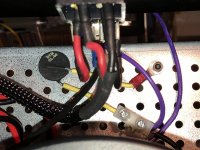
One leg of the Ground Lift Thermistor is connected to ground on the PSU, the other leg is connected to the chassis. Does it matter which leg of the thermistor goes where?
I had the ground wire from the mains going to this point on the chassis with the Ground Lift Thermistor (I use ring connectors to bolt these leads to the chassis). However, last night I changed the configuration so that the ground wire from the mains now goes directly to the PSU ground, leaving the Ground Lift Thermistor as I described it above.
Picture attached...
Attachments
Last edited:
hard to see from picture - IEC mid pin ( safety GND) must go directly to chassis, under one screw
then connect everything else , NTC from audio GND included , to same screw
lately boys elected that sole NTC isn't safe enough for purpose, so resorted to diode bridge+NTC+cap ( search for details) as more safe solution
and yes- orientation of NTC is irrelevant, same as any other resistor
then connect everything else , NTC from audio GND included , to same screw
lately boys elected that sole NTC isn't safe enough for purpose, so resorted to diode bridge+NTC+cap ( search for details) as more safe solution
and yes- orientation of NTC is irrelevant, same as any other resistor
Last edited:
My result is not exactly straightforward. The multimeter jumps from 0.000 to 0.020 every 5-10 seconds. It's not a steady 2mV AC (0.020v) but it does jump to that. Is that a problem?
.
That's bloody terrible.
Hahahaha
You have something weird going on.
My result is not exactly straightforward.
Picture attached...
The safety earth wire (from the iec connector) should be connected directly to the chassis on the other side of the thermistor, but it looks like you might have it connected on the ground lift side of thermistor.
If so this is wrong.
- Home
- Amplifiers
- Pass Labs
- F6 Illustrated Build Guide