7. Strongly recommend one of the "deluxe" chassis unless you like metal work. I'd go with 5U/400 if you have space and/or if you see yourself going down the extremely fun path of swapping out amplifiers into one chassis.
@ItsAllInMyHead - Thanks for giving further info on the things I was unsure about. I am heavily leaning towards going for a large 5U 'deluxe' as suggested, for my current build chassis. As I move on I can reuse this spacious chassis on my current project is, and move 'completed amplifiers' to something more space saving.
@intojazz - I found one of the main differences to the 'deluxe' chassis is the UMS (Universal Mounting Specification), which means the UMS heatsinks, are pre-drilled and pre-tapped to mount any of the diyaudiostore amplifier builds.
Universal Mounting Specification – diyAudio Store
From advice here, and in other threads, experienced people suggest that Deluxe 4U is a safe minimum size, and Deluxe 5U is spacious enough for almost all projects.
Last edited:
You're quite welcome. We've all been there, and I'm not too far ahead... LOL. I just started in this hobby not too long ago, and I had almost all the same questions.
Of note... re: the deluxe chassis. Also, you get the rear panels cut for you, which is wonderful. However, if you go that way... then I'd personally wait until the rear panel kit is in stock. The holes are reasonably "standard" and many parts will fit them, but it's really nice to have everything just "work" and not have to fiddle with ordering separate parts.
Also... note the difference in not only height, but length in the 4U / 300 Deluxe and the 5U / 400 Deluxe. The 5U has a lot more "growing room". Also, while the 4U/300 is a perfectly wonderful choice for an F6, having the extra length leaves not only a much more flexible space within which to work, but it also allows a much easier selection of ways to mount your power transformer further away from your signal transformer on the amp boards... which can reduce noise.
Just some affirmation that while the 5U/400 is quite large compared to some chassis options, there are many benefits over and above it simply just being easier to build in.
Here is a very useful thread: Dumb Biasing Mod, applicable to F6 and other Papa Amps. Possibly My Dumbest Idea Yet
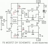
The F6 is best at higher bias currents. I run mine at 1.85 Amps per output device. It can take over an hour to reach thermal equilibrium at this bias level, unless the bias voltage references have a negative temperature coefficient. We found that three small (3mm) green LEDs worked the best. Pay attention to the direction; LEDs conduct in the forward direction, which will be the opposite of the zener symbol on the PCB.
The F6 is best at higher bias currents. I run mine at 1.85 Amps per output device. It can take over an hour to reach thermal equilibrium at this bias level, unless the bias voltage references have a negative temperature coefficient. We found that three small (3mm) green LEDs worked the best. Pay attention to the direction; LEDs conduct in the forward direction, which will be the opposite of the zener symbol on the PCB.
Just ordered most of the parts from diyaudio. Didn’t get the back panel kit as it was out of stock. Just need to take a closer look at the bom for the power supply and get that ordered.
I went with the 4U chassis and did contemplate some sort of custom front panel but decided I’d just go with the silver blank panel. So I’m all in and will be posting more as the project gets rolling
I went with the 4U chassis and did contemplate some sort of custom front panel but decided I’d just go with the silver blank panel. So I’m all in and will be posting more as the project gets rolling
rootscripts' overall planning - more lists
Your suggestion forced me to do a lot of reading yesterday, which I did not understand. However, I am bookmarking your useful info, and after i gain some experience, maybe I can understand your suggestion regarding the 'Dumb Biasing Mod'
I am making some notes/lists as I read along about components, and what they do... slowly some of this is making sense to me, but slowly. 🙂
Great that your stuff is ordered and on the way. Some of my F6 kit is now in the country, so maybe i'll get in in the next few days.
I am still here, just had an emergency on Monday (Mum went to hospital, but thankfully making a slight recovery today).
This thread helps me to keep my head above he water 🙂 and not worry like crazy about situations i cannot control.
I am waiting on tools, and have adjusted the 'Necessary tools for adjustment' List as follows:


Today, I found one post from 6LP really useful for someone with no experience (like me):
Aleph J Bias and Adjustment
The 6L6 post linked above, was one of the most enjoyable posts I have read here, it made lots of things click in to place in my mind. It is clear what he is doing, how he does it, and crucially why he does things. intojazz make sure you read it.
@6L6 - thanks for that clear walkthrough on 'Aleph J Bias and Adjustment' 🙂 Would love to know if there are more posts for 'measuring & adjustments' with relevant pictures & concise text showing how to, where to and why.
@TungstenAudio - Thanks for the suggestion, I will have to bank that advice until after I understand more about adjustments, and how to use measurements (it is a little over my head at the moment).Here is a very useful thread: Dumb Biasing Mod, applicable to F6 and other Papa Amps. Possibly My Dumbest Idea Yet
Your suggestion forced me to do a lot of reading yesterday, which I did not understand. However, I am bookmarking your useful info, and after i gain some experience, maybe I can understand your suggestion regarding the 'Dumb Biasing Mod'
I am making some notes/lists as I read along about components, and what they do... slowly some of this is making sense to me, but slowly. 🙂
@intojazzThanks guys,
Hey root,
You following?
Great that your stuff is ordered and on the way. Some of my F6 kit is now in the country, so maybe i'll get in in the next few days.
I am still here, just had an emergency on Monday (Mum went to hospital, but thankfully making a slight recovery today).
This thread helps me to keep my head above he water 🙂 and not worry like crazy about situations i cannot control.
I am waiting on tools, and have adjusted the 'Necessary tools for adjustment' List as follows:
- DC voltmeter (Found my Dad's 1980s Fluke 77, just need some good leads now). That was a fortunate find, but have a second cheap smart DMM on order for people who don't know how to use a multimeter (like me)

- AC Current limiting thing (I need to make this) with:
[**]100w 60w 40w incandescent lightbulb (to protect your build from shorts)
[**]230V AC isolation transformer to protect yourself (This heavy Schneider thing arrived today)
[**]Variac to slowly bring up the voltages in your build (Need advice to find a suitable one) - DSO to measure distortion (Maybe over the top, but this blue oscilloscope arrived today also, I have a very step learning curve ahead, it has a long manual)
- Signal generator to feed the amp a signal to measure with the DSO (Been holding off buying one, until I know the required spec for all my possible builds)
Today, I found one post from 6LP really useful for someone with no experience (like me):
Aleph J Bias and Adjustment
The 6L6 post linked above, was one of the most enjoyable posts I have read here, it made lots of things click in to place in my mind. It is clear what he is doing, how he does it, and crucially why he does things. intojazz make sure you read it.
@6L6 - thanks for that clear walkthrough on 'Aleph J Bias and Adjustment' 🙂 Would love to know if there are more posts for 'measuring & adjustments' with relevant pictures & concise text showing how to, where to and why.
Last edited:
First electronic project in 35 years. Pray for me.
As I was reading thru F6 forums, I realized this one was basically brand new. I, on the other hand, am not brand new. But I have always loved audio, and built my first and only kit in college, a Hafler 220. Amazingly it worked perfectly for years. Due to our current situation I decided maybe I should try another and having been curious as to Nelson Pass' talent as a designer, the F6 was the winning choice. I look forward to reading your experiences while trying not to cause fires with my soldering iron.
I am curious as to what some of the experienced builders used for Z1 and Z2. I believe the kit shipped with 5.1v, but it looks like most increased that to at least 5.6v.
Cheers.
^ That is how I started my F6. It a great amp to introduce oneself to Class A. The Jensen signal transformers are put to good use with this design.
The F6 will be a revelation compared to even a re-capped and updated DH-220.
The F6 will be a revelation compared to even a re-capped and updated DH-220.
Hey,
I’ve received most of the parts to begin the build already. I ordered a transformer from Antek and have been reviewing the bom for the power supply. The recommended electrolytic caps are 10000-15000 uf 35v. If the caps are in that range and fit the pcb properly nothing else changes, right? I’m asking because I see where larger value caps have been used (18000 uf). Just want to be sure before ordering.
Thanks
Thank you @ColinA123 and @TungstenAudio for that info. I noticed my kit from diyaudio included 8 zeners, and although the markings on 4 indicated 5.1v but the other markings didn't show up in a digikey search. Once I looked at the old BOM they were indeed 6.0v, so I'm all set there. Unfortunately I had soldered the 10kOhm resisters into R7and R8 before I saw that, so I'll desolder that and order the 3k3 for those spaces. Glad I bought that solder sucker.
@intojazz - You are a step ahead of me, but I was just looking at transformers yesterday and was wondering that myself. I also ordered the softstart board and the DC protection board as well, so I have to look thru those and order those parts as well.
@intojazz - You are a step ahead of me, but I was just looking at transformers yesterday and was wondering that myself. I also ordered the softstart board and the DC protection board as well, so I have to look thru those and order those parts as well.
Hey,
I’ve received most of the parts to begin the build already. I ordered a transformer from Antek and have been reviewing the bom for the power supply. The recommended electrolytic caps are 10000-15000 uf 35v. If the caps are in that range and fit the pcb properly nothing else changes, right? I’m asking because I see where larger value caps have been used (18000 uf). Just want to be sure before ordering.
Thanks
It is completely your choice re: caps. Make sure your choice of diameter and mounting parameters (snap-in) match the board. You'll see a zillion opinions.
One opinion...
If you have an inclination that you may want to do a higher power amplifier in the future using the same power supply... you might choose to get 50V rated caps. They are not that much more expensive, and will allow a bit more "future proofing". If you know that this PSU will only be used (conservatively) below 30V or so... then 35V caps are just great. All First Watt amps are ~24V rails.
Common choices are 35 or 50V rated 18kuF or 22kuF. If you can find 105 degree rated at a price you're willing to pay, they might last longer. If not... just get 85 degree rated caps and don't lose a wink of sleep.
Regarding changes to power supply bom for F6:
Built with 6.0 V Zener and R7/8 = 3k32, R11/12 = 110R and IRFP150 in the output.
I’m unclear about these parts. Is R7&R8 3000 ohm 3watt?
R11 & R12 is 110 ohm? And what is IRFP150?
And why were these changes made?
Thanks
Built with 6.0 V Zener and R7/8 = 3k32, R11/12 = 110R and IRFP150 in the output.
I’m unclear about these parts. Is R7&R8 3000 ohm 3watt?
R11 & R12 is 110 ohm? And what is IRFP150?
And why were these changes made?
Thanks
Last edited:
I did some looking and the r7 and r8 are 3.32 k ohm resistors
The 110 R is 110 ohm resistor
And the IRFP150 is a mosfet which is obsolete
What is a suitable replacement?
The 110 R is 110 ohm resistor
And the IRFP150 is a mosfet which is obsolete
What is a suitable replacement?
Regarding the power supply caps. I’m going with Nichicon 15000 uf
35 volt 105c as I’m having trouble finding anything 18000-22000uf 50 volt rated at 105c that isn’t crazy expensive.
Also I do not forsee changing this amp at all
Thanks
35 volt 105c as I’m having trouble finding anything 18000-22000uf 50 volt rated at 105c that isn’t crazy expensive.
Also I do not forsee changing this amp at all
Thanks
Still more looking reveals Mouser recommends IRFP150PBF
So I’m adding that to the list of goodies from mouser.
So I’m adding that to the list of goodies from mouser.
The R11 & R12 resistor needs to change to 110 ohm 3 watt carbon or metal film.
These are the bleed resistors for the leds
Off to mouser I go
These are the bleed resistors for the leds
Off to mouser I go
@intojazz -
Looks like you're well on your way.
You've gotten some excellent suggestions re: tweaks / mods. What I'd do were I in your shoes (and what I did)... is... build it using the parts supplied in the kit and then mod later or with a different build.
The mods suggested will not (OK one of them maaaaaay) alter the sonic signature of the amp much at all. I think even in your original post you asked how close the circuit was to the "original" First Watt design. The mods don't make it "not" an F6, but they're not as "true" to the original if that matters to you. You asked why the mods were suggested...
I'll guess... They are in-fact "good" mods... this is DIY, and there are some insanely brilliant people out there that love to modify and tweak. That's one of Nelson's gifts also... he not only "gives" these circuits to the community, I think he genuinely loves it when we fiddle with them.
What do the mods do:
Changing the Zener / R values - Can make it easier to bias. I've never had an issue using the 6V zener and the R values provided in the kit. YMMV.
"Dumb" (I think it's brilliant) biasing mod (changing zener to 3 LEDs and changing R values) - allows the amp to reach a stable bias more quickly. It's neat, but not necessary.
IRFP150 - A different output device. Neat mod for maybe a tad more power / and tweaking. Again... is it neat... yes. Is it necessary, no.
Again... if you're unsure re: the build... I'd build it exactly using the parts in the kit and using the parts designations on the store site. You really can't go wrong that way, and I think your probability of success is higher. One guy's opinion.
- Home
- Amplifiers
- Pass Labs
- F6 build