I'm talking about possible oscillations
if you don't have CRO , use this (attached) on amp output
if you see it lit , trouble is there
your smarter than my Papa!

It also allows you see thing the scope doesn't 🙄

Hey!!!
OK... I am going to make this one.
I have the transformers already at the Finnish customs service.
Will get them from there on next monday.
And, I will (already have) design my own PCB.
Anyways,
a simple question:
2SK1058?
(Which would be a nice low capacitance load for the JT123??? Or what?)
Any objections?
I tried lay fets in first version. No degeneration on bottom and .05 on top, if that. If you can match, put higher gain device below and use no source resistor on either. In Europe I would try Lundahl like Rowland uses in his amps
Make a CLC power supply! Big inductors!
Damn and I have three 100m spools of 1.5mm solid core wire... 🙁
Make a CLC power supply! Big inductors!
I have four Jantzen Audio 15mH 15 AWG P-Core Inductors - Would these be suitable?
Thanks
Bob
Looks like they are used for woofer crossovers
Specifications: • Tolerance: ± 5.0% • Inductance: 15.00 mH • Wire gauge: 15 AWG • DC resistance: 0.42 Ohms • Dimensions: 2.40" x 1.20" • Power handling: 400 watts RMS.
So if Voltage = 24V and I = 1.5A Power (VI) through should be 36W
Specifications: • Tolerance: ± 5.0% • Inductance: 15.00 mH • Wire gauge: 15 AWG • DC resistance: 0.42 Ohms • Dimensions: 2.40" x 1.20" • Power handling: 400 watts RMS.
So if Voltage = 24V and I = 1.5A Power (VI) through should be 36W
Looks like they are used for woofer crossovers
Specifications: • Tolerance: ± 5.0% • Inductance: 15.00 mH • Wire gauge: 15 AWG • DC resistance: 0.42 Ohms • Dimensions: 2.40" x 1.20" • Power handling: 400 watts RMS.
So if Voltage = 24V and I = 1.5A Power (VI) through should be 36W
I=V/R
I=1.5 A
R=.42 ohms
V= voltage drop across coil
V=I*R = 1.5*.42 =.63 V
V*I= P
P=.63*1.5 = .945 watts
Rush
Attachments

Thanks Rush and Zen Mod
Have to look for some Erse 14 guage
I think NP recommended 2mH in one of his articles - cant find it now.
Something like
ERSE-XQ
or
Copper Foil Inductor Coils | Foil Q | ERSE ?
Thanks
Bob
Have to look for some Erse 14 guage
I think NP recommended 2mH in one of his articles - cant find it now.
Something like
ERSE-XQ
or
Copper Foil Inductor Coils | Foil Q | ERSE ?
Thanks
Bob
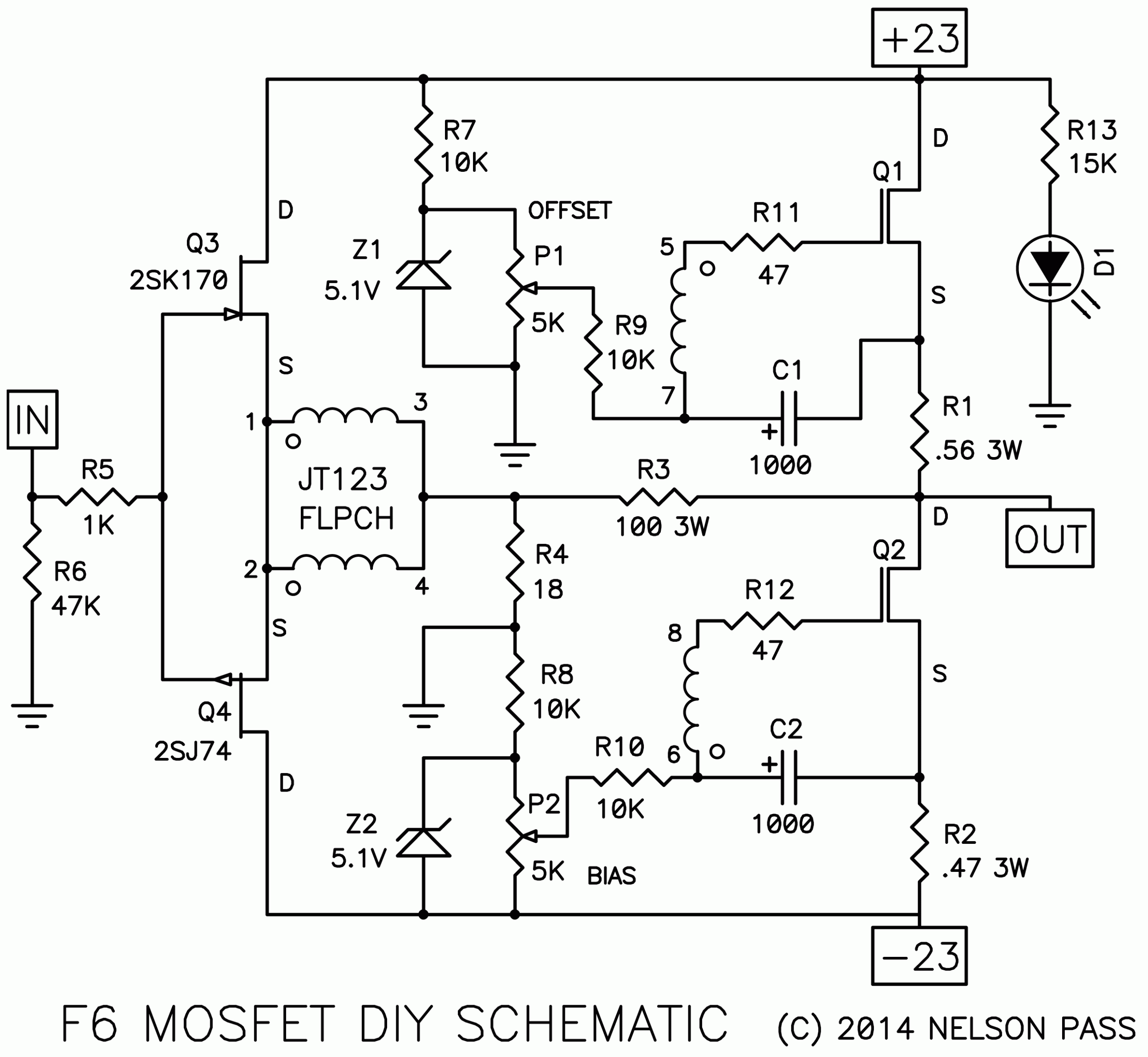
How is the temp compensation done without NTC?
will the amp drift to more idle current when hot?
will the amp drift to more idle current when hot?
go to Papa's FW site and download all pdfs , and read 😉
source resistors are there , to counteract mosfet's tempco
source resistors are there , to counteract mosfet's tempco
- Home
- Amplifiers
- Pass Labs
- F6 Amplifier