tower is temp switch
if temp in case is higher than wanted , it goes off
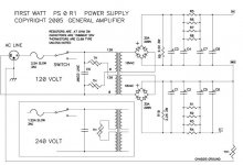
3 small caps - probably on mains etc.
don't waste time thinking of them - all you need is on published PS schm
Single Cap under the temp switch is the normal 0.0033 line cap, the two black parts over the temp switch are no "caps" but 4A mini fuses...... 🙂
Thanks Generg!
Here's the plan. 🙂 Rounding up the parts still...
https://melaveikot-sporttisaitti-com.directo.fi/@Bin/503847/F6 SketchUP.jpeg
Ok, I won't... I think. 😉don't waste time thinking of them
Here's the plan. 🙂 Rounding up the parts still...
https://melaveikot-sporttisaitti-com.directo.fi/@Bin/503847/F6 SketchUP.jpeg

I took this one
Seifert-Electronic - Products
Seifert KL-271 ; 300 x 150 x 83 mm
It's getting pretty warm 🙂
Andreas,
how much did you pay for yours? Here in Finland they are asking 83 euros a piece & 30 euros handling fees - and a 4 pcs minimum. Gets quite expensive...
For the F6 I bought the KL-271 for 60,- Euro (both) of a friend of a German community 🙂
In February we bought some Seifert heatsinks (400 x 200 x 83 mm) for other projekts and wie payed 75,- Euro.
But we picked them up (it's an one hour trip) and the amound was 12 pieces.
In February we bought some Seifert heatsinks (400 x 200 x 83 mm) for other projekts and wie payed 75,- Euro.
But we picked them up (it's an one hour trip) and the amound was 12 pieces.
Ok, just checking... I wrote Seifert and it so happens they have a distributer here in Finland, so they forwarded the email here. I had a suspicion about the price and it seems I was right. The price is more than double here..(!)
I quess I'll be making more inquieries else where...
Thanks!
I quess I'll be making more inquieries else where...
Thanks!
R13 and R14 Power Dissipation
Can someone tell me the wattage value of R13 and 14? I searched and tried to calculate it, but the Ohm's calculations don't make sense.
Ohm's Law Wheel
If I use this Ohm's law wheel, it's R * I^2=.24w, is this correct? Doesn't sound like it is. What about the voltage?
23v^2 / R{.1} = 5290w? No way.
23 x 1.55 = 35.65w? No...
I thought Ohm's law was suppose to be easy? 😕
What's missing? What's the relationship here?
Does something else need to be figured out before putting in the values into Ohm's law?
Looking at the F5 sense resistors, I see a 3w resistor.
Is 3-5w resistor close enough?
Hope this gives you good insight into the confused mind. 🙁
The voltage drop on the resistor. It is not equal to the rail voltage. Your transistors and those source resistors are sharing the same current. So you measure the current through them (when you are setting up your bias) take a square of that value and multiply by the resistance. That will give you the power.
...those source resistors are sharing the same current....
I know what you meant but that sentence can confuse vdi_nenna.
They don't share the current - current sharing occurs in parallel connection of elements.
R13 and the FET are in serial connection which means that the same amount of current flows through both of them (if we neglect the 10R pot because it is 100 times the value of R13).
Otherwise you are right.
That's exactly what I mean, thanks 🙂!
10R pots I do not even have them in my F6 🙂 I forgot about them of course 🙂
10R pots I do not even have them in my F6 🙂 I forgot about them of course 🙂
I still don't get it. I can't get the math to work.
It doesn't come out. Just doesn't work for me.
It doesn't come out. Just doesn't work for me.
Last edited:
Which part of it?
In a most simple case you have a series connection between the FET(R_f) and that 0R1 (R) resistor.
You have a voltage applied to pith of them as an equivalent single resistor(FET= resistor here). So you have the current goes through both of them which will be calculated according to Ohm's law you mentioned U/(R_f+R). This will be the current. Assuming that the charge do not accumulate in the series you will have equal current going through R_f and R. (think of it as incompressible liquid flux going through the pipe with no leakage). So you know the current. Now you can calculate the dissipation by I^2*R. (Sorry if I sad something too obvious 🙂
vdi_nenna,
in serial circuit the same current (I) flows through all elements of that circuit, but the voltage across each element is proportional to that element's resistance. So, if the bias current (set by 5k pot) is 1.2A, the same current goes through 0R1 resistors (R13,14) and each of those resistors will dissipate 1.2A x 1.2A x 0R1 = 1.44 x 0.1 = 144mW
The voltage across those 0R1 resistors will be equal to 1.2 x 0.1 i.e. 120mV
Run those values through Ohm's Law wheel few times and you'll see that it holds...
In parallel connection elements are exposed to equal voltage but the current through each of them will be proportional to their resistance (I=U/R).
Run an experiment with a battery, couple of resistors and a DMM and a new age (the rule of the Ohm's Law) will dawn upon you. 🙂
How is it with audio toroidal transformers and magnetic stray fields - is stacking them like this in a dual mono configuration OK? Any temperature problems?
https://www.facebook.com/photo.php?...29169456.10665.100001684484838&type=3&theater
https://www.facebook.com/photo.php?...29169456.10665.100001684484838&type=3&theater
- Home
- Amplifiers
- Pass Labs
- F6 Amplifier