Is it a current article introducing a new amp?
It is an article by Jean Hiraga in L'Audiophile, no. 15 (nouvelle série), april 1991. NOI: new old idea.
The secondary is connected on the top of the zener so only a little bit of bias current (would it be 50 nA in the F6?) flows through the winding.
Good nights rest and I figured it out in split. I had mistakenly messed up primary wiring effectively cancelling the signal on the primary side. Still dead quiet. Couldnt really get a good listen since kiddos were still in bed, so more later.
Cant wait to crank it up. Got to get me another breadboard so I can play around having both channels working. What value zen pot? 20R?
skip zen pot
wire as I sent ya , ditto on source
if you insist on zen pot - no more than 100R
wire as I sent ya , ditto on source
if you insist on zen pot - no more than 100R
I will not insist. Wired as sent. I will vary Rs between .47 and .22 and see if it is noticable. I will eventually measure, but want to listen and see if i can say what it will show before it is done. I had to use 470R on gates to handle small oscillation with just output hooked up and no FE. I had 47R originally. Perhaps they could be reinstated with GFB use. Will try.
Rs is important from two reasons - bias stability , and dynamic influence .
you can delete entire modulation mechanismus ( xformer) and Rs is still in place where needs to be , regarding bias and it's stability
dynamic influence - even if not accounted in xconductance of part itself , it ads to output impedance of amp , contributing to THD form
regarding bias and it's stability:
Pic A there is dc bias stabilisation.
Pic B i see none. (Or it's mechanism is unknown to me.)
Attachments
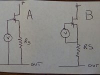
make diff between bias and modulation path
biasing pot is situated between gate and bottom of Rs
modulation path is situated between gate and source
both schmtcs posted by me , same as lhquam's , are as your case A
biasing pot is situated between gate and bottom of Rs
modulation path is situated between gate and source
both schmtcs posted by me , same as lhquam's , are as your case A
Last edited:
Bingo!
That's true for Dc.
And that's where i was blind.
I was seeing it as B pic.
Thx for your patience.
That's true for Dc.
And that's where i was blind.
I was seeing it as B pic.
Thx for your patience.
I am now using the pic A for AC and pic B for DC. Rs=0R12. Bias is perfectly stable and it sounds good. See schematic in post #1647 http://www.diyaudio.com/forums/pass-labs/216616-f6-amplifier-165.html#post3159810.
make diff between bias and modulation path
biasing pot is situated between gate and bottom of Rs
modulation path is situated between gate and source
both schmtcs posted by me , same as lhquam's , are as your case A
I am now using the pic A for AC and pic B for DC. Rs=0R12. Bias is perfectly stable and it sounds good. See schematic in post #1647 http://www.diyaudio.com/forums/pass-labs/216616-f6-amplifier-165.html#post3159810.
you mean other way around (bobo's pics in #1668 ; A for DC (bias) , B for AC (modulation)
 ?
?no need for more confusion , your schm (linked above ) is crystal clear
.....
both schmtcs posted by me , same as lhquam's , are as your case A
of course , I meant - regarding bias
My bad. Too early in the morning here.
you mean other way around (bobo's pics in #1668 ; A for DC (bias) , B for AC (modulation)
no need for more confusion , your schm (linked above ) is crystal clear
Sorry for making confusion. I am so thick.
ZM, i see you keep a big cap across biasing diodes. I remember Papa said to take them off when Ihquam was troubleshooting his motorboating.
Ihquam, where this motorboating came from at the end, you did'nt tell really, i think?
ZM, i see you keep a big cap across biasing diodes. I remember Papa said to take them off when Ihquam was troubleshooting his motorboating.
Ihquam, where this motorboating came from at the end, you did'nt tell really, i think?
Last edited:
I have a drawer full of 470uF/35V/125C industrial Elna's
for my ears , they're same as BG well broken in , both bypassed with 10n-1uF MKC
so , stubborn or what , I'm seeding them and green LED's wherever I can .......
there will not be breathing , when fed with CCS
for my ears , they're same as BG well broken in , both bypassed with 10n-1uF MKC
so , stubborn or what , I'm seeding them and green LED's wherever I can .......
there will not be breathing , when fed with CCS
The moterboating problem went away when I increased the size of the bias caps from around 22uf up to 470uf. I am not 100% convinced that there isn't the possibility for oscillation, but the frequency now will be below about .05 Hz. Also, the motorboating was seen in a somewhat different circuit shown in post #941 http://www.diyaudio.com/forums/pass-labs/216616-f6-amplifier-95.html#post3133892. In principle, that circuit should perform similarly to the current one. Looking at the Spice AC analysis, there were very low frequencies where the phase margin was questionable.
Sorry for making confusion. I am so thick.
ZM, i see you keep a big cap across biasing diodes. I remember Papa said to take them off when Ihquam was troubleshooting his motorboating.
Ihquam, where this motorboating came from at the end, you did'nt tell really, i think?
"there will not be breathing , when fed with CCS"
So you have experienced a similar low frequency oscillation. How much modulation of the bias voltage (or current) have you seen? Do you fully understand the feedback mechanism?
So you have experienced a similar low frequency oscillation. How much modulation of the bias voltage (or current) have you seen? Do you fully understand the feedback mechanism?
I have a drawer full of 470uF/35V/125C industrial Elna's
for my ears , they're same as BG well broken in , both bypassed with 10n-1uF MKC
so , stubborn or what , I'm seeding them and green LED's wherever I can .......
there will not be breathing , when fed with CCS
The transformer secondaries are set up to drive the Fets in a matched
fashion, if that is what you're asking.
The Fets can be a wide variety of devices. In this case, R100's.
I no longer apply for patents.
I haven't seen this feedback mechanism as such, but you can be
sure it's been done one way or another, probably a long time ago.
😎
I've played with a very similar idea about 7 years ago and exchanged some emails about it with Ben Dunkan. Here is the basic circuit. At the time I couldn't find a similar feedback circuit - at least not in LF applications, however I also thought that something like this has been done a long time ago.
Cheers
Alex
Attachments
Preliminary results make me think less feedback, not more. I currently have .47Rs, bias of 1.3A per fet, 8dB of gain. I have some 330R mills, so Iam gong to try that. BTW, Bypass cap is necessary. I have 1K Nichicon Muse and they add their electro sound to the amp. Don't stone me please. I have some 470uF Silmic II's to try. I will be byassing with fancy Film more than likely. Although i cant grasp why you would want to do so considering the balanced nature of the circuit, I have considered putting two resistors in series to form the Rs Total. Put pot across top one and pull modulation point from their. Wouldnt lose all you DF and would allow for Zen adj.
- Home
- Amplifiers
- Pass Labs
- F6 Amplifier