this one is biger
Because of my poor English, only with the help of the dictionary, so pretty. Same meaning, can you guess right, I'm sorry.
Because of my poor English, only with the help of the dictionary, so pretty. Same meaning, can you guess right, I'm sorry.
An externally hosted image should be here but it was not working when we last tested it.
always interesting again....🙂
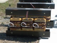
two channels with four closely Vgs matched R125....in a constellation with a Cinemag xformer.
........thanks tea-bag really fine sound........! 🙂
would be interesting if these differences are gone with pairs better matched by a curve tracer...
of course I will do place hopping 😀
Those look like very very tiny differences no? I am guessing it will be hard to get much closer unless the amps tested were hi fb kinds...
Also these were after trimming pots or no trim ? If latter maybe worth swapping the fets between channels to see what happens.
@kiven chen
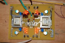
you need fatter traces - for power (both + and - ) , and for loudspeaker output
besides that - I hate checking even my own pcbs ....... so no help in that , from me .
you need fatter traces - for power (both + and - ) , and for loudspeaker output
besides that - I hate checking even my own pcbs ....... so no help in that , from me .
Thank you for your help, the power and speakers I will add copper on the PCB.
Because I was set on the radiator, the radiator is only 120 mm high, so I use 35 mm PCB
Because I was set on the radiator, the radiator is only 120 mm high, so I use 35 mm PCB
🙂
Hi kasey,
without trimpots and 0R1 resistors....
indeed after changing the places of the SS in the channel that had k3 dominant, the situation changed and the k2 got dominant (about 6db). The other channel has a k2 dominance of 12 db.
I have the impression that the dominance of k2 or k3 is hearable, but do not fix me at which db point, 6 or 8 or 12......
With my J2 tries I dare to say that the difference of 14 or 8db k2 dominance is perceptible (to me.... 🙂?)
the F6 excels in in a huge stage....
but what a pleasure to hear with the First Watt line so many different good sounds and amps.... I can´t stop changing.....🙂
Those look like very very tiny differences no? I am guessing it will be hard to get much closer unless the amps tested were hi fb kinds...
Also these were after trimming pots or no trim ? If latter maybe worth swapping the fets between channels to see what happens.
Hi kasey,
without trimpots and 0R1 resistors....
indeed after changing the places of the SS in the channel that had k3 dominant, the situation changed and the k2 got dominant (about 6db). The other channel has a k2 dominance of 12 db.
I have the impression that the dominance of k2 or k3 is hearable, but do not fix me at which db point, 6 or 8 or 12......
With my J2 tries I dare to say that the difference of 14 or 8db k2 dominance is perceptible (to me.... 🙂?)
the F6 excels in in a huge stage....
but what a pleasure to hear with the First Watt line so many different good sounds and amps.... I can´t stop changing.....🙂
the F6 excels in in a huge stage....
Its most notable feature, IMO.
I have a pilot run of 20 pieces for in-house use and to share with my buddies.
I simply tested the Jfets for transconductance and use that to roll the 2nd
harmonic.
😎
I simply tested the Jfets for transconductance and use that to roll the 2nd
harmonic.
😎
I have a pilot run of 20 pieces for in-house use and to share with my buddies.
I simply tested the Jfets for transconductance and use that to roll the 2nd
harmonic.
😎
With the higher transconductance parts in the upper half ?
Welcome back btw ...
The new schedule, PCB has been completed.
An externally hosted image should be here but it was not working when we last tested it.
Go for throttle up.Kiven,
Be careful of pinout😀
Glas I decided to fire up bias arrangement first. Hadnt noticed board layout issue. All corrected now and will soon be moving forward, after lunch.
With the higher transconductance parts in the upper half ?
There are three possibilities. I will do all three, and listen to each with a
different wine.
😎
Kiven,
Be careful of pinout😀
Glas I decided to fire up bias arrangement first. Hadnt noticed board layout issue. All corrected now and will soon be moving forward, after lunch.
Thank you for your remind:
I think, the output near the feedback sampling resistance is better, the power near MOSFIT is also better. Isn't it?
An externally hosted image should be here but it was not working when we last tested it.
There are three possibilities. I will do all three, and listen to each with a
different wine.
😎
All Cabs? 😉
There are three possibilities. I will do all three, and listen to each with a
different wine.
😎
I don´t have three different wines.....and only one upper and one lower place...
you are privileged.......😀😀😀
May be a wiring problem,one channel 20MHz Self-excited, negative feedback 100 Ohm resistor in parallel with a 100P small ceramic capacitors are normal. Another channel is fine.
I'm confused - why do you guys balance the F6 by mirroring everything? I mean, the transformer used for phase splitting could be fed a balanced input (you'd maybe need another set of Q3/Q4 and some resistors). Is there an intrinsic advantage to the fully-mirrored design, instead of having the distortions cancel ea. other out in the same transformer? I could see it in the case of the BA3, but the F6 transformer design is intrinsically balanced. Am I missing smtg?
- Home
- Amplifiers
- Pass Labs
- F6 Amplifier