Extra pads would be fine, long as the Jensen can be mounted on the board since I imagine most will opt for the original X-former.
I would pay a small premium to help the designer lower costs. I prefer PCB over P to P.
Regards,
Dan 🙂
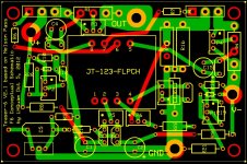
Anyone thinking about F6 PCBs?
Regards,
Dan 🙂
Attachments
Confirming pinouts are different for the Onetics. Hopefully I can be listening before leaving for Seattle on Monday
O.K. here comes the minority report for ZM....
ISKRA has lowest THD in my measurements, a small bit lower than Jensen....
means 0,004% smaller....🙂
because k2 is still lower than the k2 of Jensen. Buzz said this could be sign of the similarity of windings....
k3 is a bit higher than the k3 of Jensen....
so if I increase the k2 to surpass the k3 about 6db I get with the ISKRA a bit more THD than with the Jensen, that may be the reason I find the ISKRA a bit more detailed and less dry.
🙂

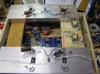
I hope you will like PtP.....!
Do not forget to put an 500R or 1k pot nearby to put it parallel to the upper secondary if you should need some more k2....😀
May I all ask again....?
The original circuit Nelson gave us had in my build k3 and k2 on the same level,
is this intended or due to my build and parts?
Shouldn't k2 be dominant per se? My second channel even had k3 higher than k2.
I am sure it is similar to the J2, in that all the parametrs matter. Isnt ig the easiest amp to play around with. Have you tried switching the phase of yhe top and bottom secondaries?
you're begging for positive feedback ?
that way is easy to have buzzzzzz ............ and big badabooooom , if you're using sissy speakers

that way is easy to have buzzzzzz ............ and big badabooooom , if you're using sissy speakers
Common F6 schematic suggested
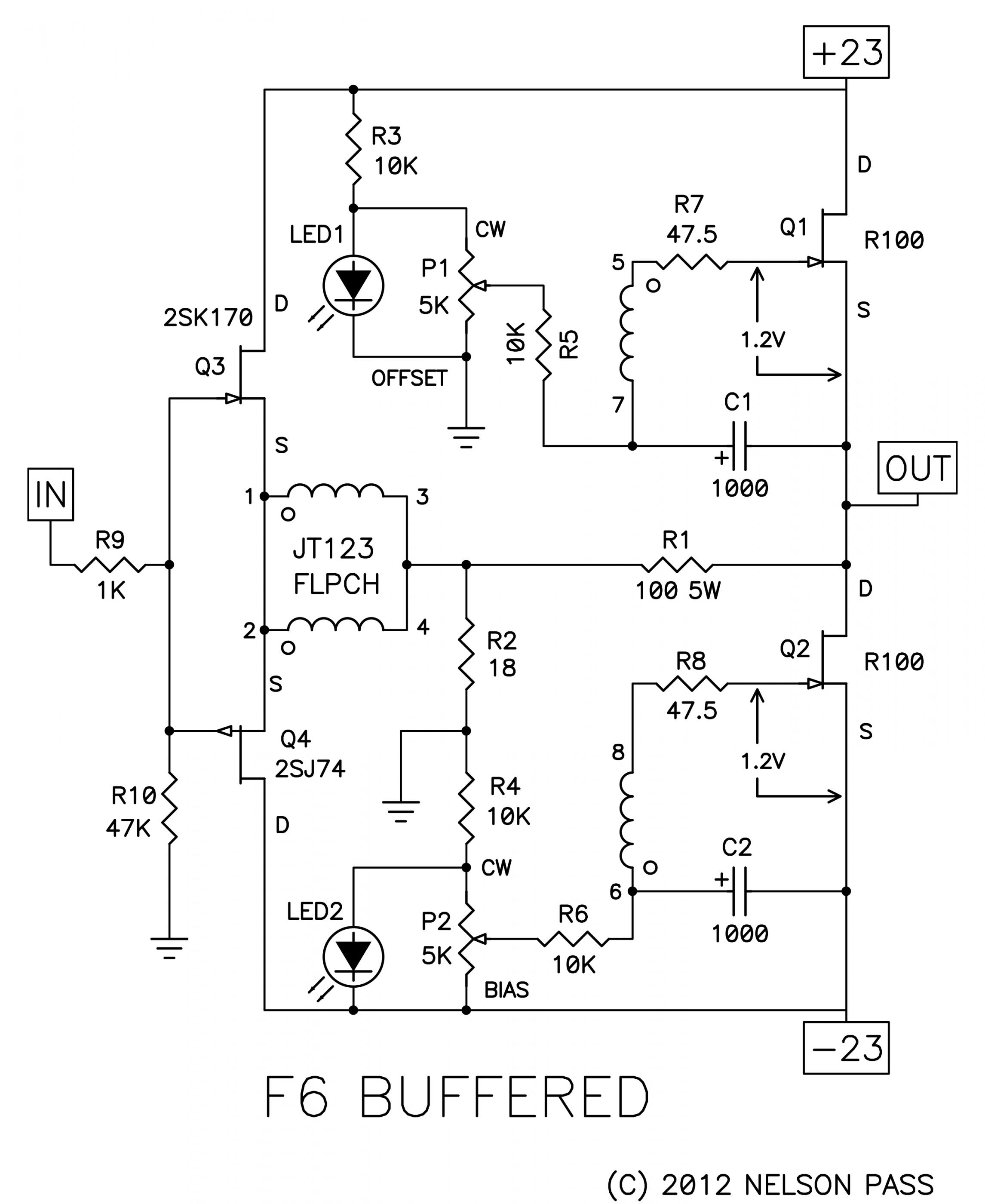
I suggest that we agree on a common F6 schematic, including optional parts (like Zen pots) so that we can refer to components unambiguously. The component values do not necessarily need to be shown, only the component identifiers, like R1 and P3.
The main divergence might be in the area of the bias circuits and voltage generators for the input followers.
Any opinions?
Can we use the official schematic as a basis for a PCB for the masses? There will alway be others that customize and diverge from the original. Perhaps a base motherboard with daughterboards for options? Too elaborate?
Regards,
Dan 🙂
What official schematic? The only schematic from Papa since post #1 (and a later correction) is a photo of the projection screen at BAF. In any case, these schematics do not provide enough common options for DIYers to experiment with.
Post 2588 by Nelson Pass
Now that the cat's out of the bag via BAF, here is the official F6 schematic.
Regards,
Dan 🙂
didn't we put enough variables already ?
perfect tutorial to everyone to make his own drek

Dan - here is da link : http://www.diyaudio.com/forums/pass-labs/216616-f6-amplifier-130.html#post3225569
and pic :
perfect tutorial to everyone to make his own drek
Dan - here is da link : http://www.diyaudio.com/forums/pass-labs/216616-f6-amplifier-130.html#post3225569
and pic :
Last edited:
from generg
"I hope you will like PtP.....!
Do not forget to put an 500R or 1k pot nearby to put it parallel to the upper secondary if you should need some more k2...."
thanks generg - I will be trying it this weekend and then see if I can shorten leads, etc - I want to build on a set of Jensens to compare. I will then re-read the fine tuning info and see what I can do
from generg
"Do not forget to put an 500R or 1k pot nearby to put it parallel to the upper secondary if you should need some more k2...."
I went back and read the zen pot info as well as all I could find on the F5s P3
generg referring to post 2837 - am I correct in saying you are suggesting a 500 or 1k pot across pins 5 and 7 of the transformer
Thanks
Bob
from generg
"Do not forget to put an 500R or 1k pot nearby to put it parallel to the upper secondary if you should need some more k2...."
I went back and read the zen pot info as well as all I could find on the F5s P3
generg referring to post 2837 - am I correct in saying you are suggesting a 500 or 1k pot across pins 5 and 7 of the transformer
Thanks
Bob
yes around these values, 500R to 1000R and I recommend you to look at Ihquams experiments with this, he did all months earlier....😀
and really adding 8-12 db higher k2 than k3 is for me substantial to get the best out of the circuit so the pots are a must for me!
- Home
- Amplifiers
- Pass Labs
- F6 Amplifier