Thank you Buzz for your help!
I think the curves look odd because of the measurement conditions.
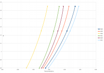
As I have mounted the JFets on a heatsink, and not as EUVL suggested on a massive aluminium block (~3kg, ideally with OID controlled heating), the upper part of the curves are more "to the right": Here the heatsink is hot (but touchable, 50°C), so the JFets are needing more V_GS for the same Drain current. This is why in the reagion from roughly 1.4A till 2.0A the curves are flatter, moreto the right. Here the transconductance is lower as when the heatsinks and therefore the JFets would been at room temperature.
While I took the other datapoints, the heatsinks cooled down, even if just from max 55°C to 35°C, the curves there represent a higher transconductance. The JFets are cooler, so they need lesser V_GS for the same I_D.
As a conclusion, I would guess, that the curves should have all the same shape (more or less), but that the "distance" in V_GS shows their different behaviour.
For example, the shape of the curves of #229 and #206 are odd, but I have measurements where they look identical. But I used this datapoints, because the conditions for measurement have been the most equal.
I think the curves look odd because of the measurement conditions.
As I have mounted the JFets on a heatsink, and not as EUVL suggested on a massive aluminium block (~3kg, ideally with OID controlled heating), the upper part of the curves are more "to the right": Here the heatsink is hot (but touchable, 50°C), so the JFets are needing more V_GS for the same Drain current. This is why in the reagion from roughly 1.4A till 2.0A the curves are flatter, moreto the right. Here the transconductance is lower as when the heatsinks and therefore the JFets would been at room temperature.
While I took the other datapoints, the heatsinks cooled down, even if just from max 55°C to 35°C, the curves there represent a higher transconductance. The JFets are cooler, so they need lesser V_GS for the same I_D.
As a conclusion, I would guess, that the curves should have all the same shape (more or less), but that the "distance" in V_GS shows their different behaviour.
For example, the shape of the curves of #229 and #206 are odd, but I have measurements where they look identical. But I used this datapoints, because the conditions for measurement have been the most equal.
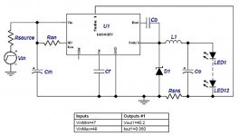
Am I right, that lm329 has reversed polarity compared to LED?
No more questions now.
Yes.
Was this an inside joke? or should one point the arrow the other way when using the regulator instead of an LED?
Or just follow the schematic and the datasheet for the LM329?
Please note, I am a complete idiot to electronics. (And for everything else, but that's not important right now.)
As I understand it, the LED forward voltage is giving you about 1.8-2.5 Volt across it.
LM329 a zener-like device, with reverse breakdown voltage about 6.9 Volt, with better characteristics.
So you have with it a broader setting window.
If I missed something, there are smarter ones, who can correct me.
Last edited:
Hello Gyuri,
thanks for you patience and help.
I've one last question, do you mount P3 and P4 or only P4 and how do you trim them?
Ciao
Guglielmo
This is for you, Guglielmo:
https://onedrive.live.com/redir?resid=E894CB7D50B65FBF!1164&authkey=!9!rkr!r0TZw%24&v=3&ithint=photo%2cJPG
This is a follow-up post from #96.
As I measured my Power JFets 4 times but got a variation too big for my taste and also to use the measurements as basis for a conclusion, I scratched my head a long time wondering how I can do this better.
And, re-inventing the wheel, I stumbled once again over Nelson's article on how to match mosfets (the one with the testing rig).
As I don't own a signal generator as input device for the 0,1V 1kHz sinus, I used my soundcard for this. With audacity (opensource, very good) I created a 1kHz sinus wave, 10 mins, and saved this into a 24bit flac.
The rest is more or less a free interpretation of Nelson's circuit. Thank god I had a 8ohm 300watt resistor, this came in handy! 😀
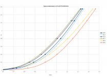
So, attached you find 2 pictures, the first showing the transconductance in the usual way (ID over VGS), the second one the transconductance calculated with the formula in Nelson's article, over ID. Here you can see very nicely the variating shape of the transconductance, if current is variated.
Ah, and the measurements were taken with V_DS=22V, all the same room temperature (it has been very cold here in Sao Paulo, just 16°C outsides).
So, I decided to choose #229 and #221, and for the other channel #212 and #206. They have a similar curve shape and also are behaving more or less equal, if you compare the matches.
If I'm taken the "wrong" sets, please correct me, I'm here to learn and pleased for a different opinion. If I did everything as you would have also done, then I'm happy to hear this also!
As I measured my Power JFets 4 times but got a variation too big for my taste and also to use the measurements as basis for a conclusion, I scratched my head a long time wondering how I can do this better.
And, re-inventing the wheel, I stumbled once again over Nelson's article on how to match mosfets (the one with the testing rig).
As I don't own a signal generator as input device for the 0,1V 1kHz sinus, I used my soundcard for this. With audacity (opensource, very good) I created a 1kHz sinus wave, 10 mins, and saved this into a 24bit flac.
The rest is more or less a free interpretation of Nelson's circuit. Thank god I had a 8ohm 300watt resistor, this came in handy! 😀
So, attached you find 2 pictures, the first showing the transconductance in the usual way (ID over VGS), the second one the transconductance calculated with the formula in Nelson's article, over ID. Here you can see very nicely the variating shape of the transconductance, if current is variated.
Ah, and the measurements were taken with V_DS=22V, all the same room temperature (it has been very cold here in Sao Paulo, just 16°C outsides).
So, I decided to choose #229 and #221, and for the other channel #212 and #206. They have a similar curve shape and also are behaving more or less equal, if you compare the matches.
If I'm taken the "wrong" sets, please correct me, I'm here to learn and pleased for a different opinion. If I did everything as you would have also done, then I'm happy to hear this also!
Attachments
- Status
- Not open for further replies.
- Home
- Amplifiers
- Pass Labs
- F6 amp with SemiSouth SJEP120R100