🙂
Second batch won't be same price, I am afraid.
Doing it once for charity is enough, considering the huge effort required that you do not see.
So those who had blind faith in me are duly rewarded.
Lucky Horio. 😉
Patrick
Second batch won't be same price, I am afraid.
Doing it once for charity is enough, considering the huge effort required that you do not see.
So those who had blind faith in me are duly rewarded.
Lucky Horio. 😉
Patrick
my guess on the lines are a change in density caused either in manufacturing or by clamping during machining . were those lines visible prior to anodizing ?
cheers Woody
cheers Woody
We really don't know the reason yet. We change material supplier and we'll try to machine differently for the coming "test" piece. For this 30 pieces, I've seen them after brush but before anodizing, not after CNC machining. I didn't notice there are lines on the surface.
Usually CNC clamping is at the side walls.
We'll see in a week's time hopefully. (Finger crossed)
Mark
Usually CNC clamping is at the side walls.
We'll see in a week's time hopefully. (Finger crossed)
Mark
What is the price of the machines parts. I am looking to get some done and need a reference point.
Option 2 of the F5X case GB, which includes all cutouts and internal parts is 360 Euros without Conrad heat sinks, and without shipment costs, is 360 Euros.
Bear in mind this is volume price and we make no profit.
So commercial, one-off price is likely to be substantially higher, if you can find someone who can do it to the quality and is interested at all, that is.
And no, our factory is too busy to do any more machining service this year, even if price is not an issue for you.
Sorry to disappoint you, but thank you for your interest and appreciation.
Patrick
Just wondering if the reject parts will be offered at lower price instead of being thrown away.
No.
You don't get reject parts from Porsche or Ferrari or Rolls Royce .....
Not even from Toyota's.
😉
Patrick
You don't get reject parts from Porsche or Ferrari or Rolls Royce .....
Not even from Toyota's.
😉
Patrick
No.
You don't get reject parts from Porsche or Ferrari or Rolls Royce .....
Not even from Toyota's.
😉
Patrick
I don't know about that. I bought my Maserati from the President of the company as a second. I saved a lot of money that way.
I guess it worked out in the end, I wrecked it doing three times the speed limit...
No.
You don't get reject parts from Porsche or Ferrari or Rolls Royce .....
Not even from Toyota's.
😉
Patrick
Well - you also never get these at below cost of production😀
Heya fellows, regarding the 2SK1530/2SJ201 matching, the 4 devices in each channel should be tightly matched, but does both left & right channel needs similar tight matching as well?
cheers
cheers
No, the matching in only important within one channel, as fars the functioning of the circuit is concerned.
But then you probably also want the left channel to be reasonably identical to the right one ??
😉
Patrick
But then you probably also want the left channel to be reasonably identical to the right one ??
😉
Patrick
No, the matching in only important within one channel, as fars the functioning of the circuit is concerned.
But then you probably also want the left channel to be reasonably identical to the right one ??
😉
Patrick
Thanks Patrick, my quad set matched values at 1.3A are:
Right channel
---------------------
2SK1530 pair | 2SJ201 pair
2.326V/2.326V | 2.324V/2.326V
Left channel
---------------------
2SK1530 pair | 2SJ201 pair
2.337V/2.341V | 2.340V/2.341V
I hope they close enough. I have to say this is the most professional looking DIY project I've encountered. Thank you for letting us participate in the fruits of your labor.

Yes, close enough.
Because of thermal drift during measurements, I do not believe in matching better than 5mV.
unless of course you used a temperature controlled heater block to set the MOSFET at operating temperature.
Patrick
Because of thermal drift during measurements, I do not believe in matching better than 5mV.
unless of course you used a temperature controlled heater block to set the MOSFET at operating temperature.
Patrick
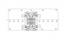
Heat Sink Temperature Distribution
Somehow we have not heard from Melon Head all these days.
And I was still hoping for a temperature distribution measurement.
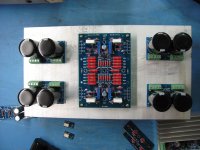
Luckily our prototype is functional today, and Mark has kindly taken the time to do a measurement.
As you can see, my simulations were not too far off.
Measurements were taken 1 hour after power on, with +/-16V rails, 4A bias.
🙂
Patrick
Somehow we have not heard from Melon Head all these days.
And I was still hoping for a temperature distribution measurement.
Luckily our prototype is functional today, and Mark has kindly taken the time to do a measurement.
As you can see, my simulations were not too far off.
Measurements were taken 1 hour after power on, with +/-16V rails, 4A bias.
🙂
Patrick
Attachments
The simulated I did a while ago can be found here :
http://www.diyaudio.com/forums/pass-labs/172770-balanced-f5-question-7.html#post2346379
Patrick
http://www.diyaudio.com/forums/pass-labs/172770-balanced-f5-question-7.html#post2346379
Patrick
Looks like the simulations were pretty close. The edges furthest away from the FETs aren't as warm as the simulation suggested, but that's probably due to the closer grouping of the parts toward the center of the sink.
I guess the most important part, are the temperatures around the FETs themselves, and those look to be close to what you were anticipating. 🙂
I guess the most important part, are the temperatures around the FETs themselves, and those look to be close to what you were anticipating. 🙂
> Looks like the simulations were pretty close.
I said before that simulations are accurate to within 2°C.
Just people do not want to believe.
😉
> The edges furthest away from the FETs aren't as warm as the simulation suggested,
> but that's probably due to the closer grouping of the parts toward the center of the sink.
Actually due to additional heat sinking by the front & rear panels.
Patrick
If the model is good (= close to reality) and the simulation is good (= close to reality), then the prediction should be close to reality.
It's when the model is poor or the calculation method is poor that the prediction can be much worse than poor, or fluke upon a chance answer that is close to good.
The user has to determine the reliability of the simulation before the user can rely on the predictions. That is fundamental to all software used in engineering design. One must be able to check that the predictions are close to correct.
Somehow we have not heard from Melon Head all these days.
Melon Head has not logged into diyAudio since April. Hopefully he just lost interest (members come and go), but this seems unlikely for a prolific poster.
- Home
- Amplifiers
- Pass Labs
- F5X -- the EUVL Approach