> So I am wondering if other F5X DIYers were already brave enough to do a listenting test with and without speaker protection relays and if they could confirm our findings.
Use the relay in shunt; then it is not invasive.
Patrick
Use the relay in shunt; then it is not invasive.
Patrick
On the F5 I nave put any relay, so far never had a problem.
The reason while I am a bit skeptical about the shunt is that the DC output could be due to DC in input in this amp, so you may destroy a perfectly working amp.
I guess it all depends on the price of your speaker, if it's many times higher than the F5X, it may make sense, otherwise better destroy the speakers than the amp.
D
What would be against putting a "proper" relay in the power line? (not as a shunt but in series just after the power supply capacitors)
What would be a "proper" relay ?
I agree that switching off power after the CregC caps is not a bad idea.
You do add some noise to the rails, but you can add a small MKP (say 2µF) after the relay.
AND you want to use DPDT at that position, minimum 8A.
When a differential DC is detected by the protection board, it will :
1) shunt the inputs to Gnd AFTER the 1k input resistors (so your source is now loaded by 1k per phase & not 101k);
2) switch off the regulators by shunting the regulator MOSFET gates to (almost) Gnd;
3) switch off your main transformers (the aux transformer is still on);
4) energise the speaker relays (with a slight delay due to the slower response of the latter).
Your source must be very bad to have 0.3V differential DC, not true ?
So if the protection board trips,
a) you already put inputs to Gnd before you short circuit the output, so your differential outputs should already be zero;
b) you already switch off power, so you only have the energy of the caps after regulator to get rid of;
d) given that you do have a fault in amp, you want to replace any damaged MOSFET as a set anyhow;
e) you can always install the current limiting circuit on the amp PCB to save your MOSFETs.
So I personally do not see any issue of using shunt at the speaker side.
And yes, my speakers are a lot more expensive than 8 MOSFETs.
But you should not blindly copy what I do.
You have enough options.
Patrick
Last edited:
And IF I were to switch after CRegC onstead of at speaker output, I would probably use
1x FINDER 41.52.9 24V
2x EPCOS B32923C3155M
per channel.
Patrick
1x FINDER 41.52.9 24V
2x EPCOS B32923C3155M
per channel.
Patrick
I don't recall reading this in the Threads.................When a differential DC is detected by the protection board, it will :
1) shunt the inputs to Gnd AFTER the 1k input resistors (so your source is now loaded by 1k per phase & not 101k);
2) switch off the regulators by shunting the regulator MOSFET gates to (almost) Gnd;
3) switch off your main transformers (the aux transformer is still on);
4) energise the speaker relays ..........................
So if the protection board trips,
a) you already put inputs to Gnd before you short circuit the output, so your differential outputs should already be zero;
b) you already switch off power, so you only have the energy of the caps after regulator to get rid of;...............
Was I asleep, or just my bad memory?
re post780
Any clarification coming for the relay specifications and the relay driving voltages?
Any clarification coming for the relay specifications and the relay driving voltages?
http://www.diyaudio.com/forums/pass-labs/208880-f5x-euvl-approach-build-thread-5.html#post3269256
http://www.diyaudio.com/forums/pass-labs/208880-f5x-euvl-approach-build-thread-6.html#post3313639
http://www.diyaudio.com/forums/pass-labs/208880-f5x-euvl-approach-build-thread-10.html#post3399396
Patrick
http://www.diyaudio.com/forums/pass-labs/208880-f5x-euvl-approach-build-thread-6.html#post3313639
http://www.diyaudio.com/forums/pass-labs/208880-f5x-euvl-approach-build-thread-10.html#post3399396
Patrick
I have gone through all the Fitzfish posts from October 2012 and none contain a BoM nor the possible updated BoM referred to here:
http://www.diyaudio.com/forums/pass...ach-build-thread-post3266543.html#post3266543
http://www.diyaudio.com/forums/pass...ach-build-thread-post3266543.html#post3266543
He has not, but I cannot change anything because it is his document. In fact this is his thread.
But my protection circuit description already explained that the relay has 24V supply.
And I am sure you know how to connect 2x 12V if you wish to.
So there is no technical difficulty I guess.
If you are pushing for proper documentation, then you need to refer to the corresponding authors.
This is particularly the case for Batch 1, since it is a joint effort from many people.
For Batch 2 we (XEN) are solely responsible for everything, so we also supplied all documents.
There are however changes in Batch 2 that are not identical to Batch 1.
So those documents are not relevant for you, and we shall NOT release them to batch 1 builders as they would create more confusion.
Patrick
I have looked through all my saved F5x files and cannot find the Fitzfish BOM.
I was on holiday for 6weeks in the middle of 2012. I may have missed it, or when I was trying to catch up after being away so long.
Can anyone point me to the most recent Batch1 BoM?
I was on holiday for 6weeks in the middle of 2012. I may have missed it, or when I was trying to catch up after being away so long.
Can anyone point me to the most recent Batch1 BoM?
I have found and saved the post39 BoM.
But much is missing.
Only one relay mentioned and it is 24V (Z2608-ND)
whereas I have 12V relays for the input mute.
I have no other relays.
I am obviously missing much, since you are all referring to at least 4 different relays.
What is the drive voltage for the input mute relay?
But much is missing.
Only one relay mentioned and it is 24V (Z2608-ND)
whereas I have 12V relays for the input mute.
I have no other relays.
I am obviously missing much, since you are all referring to at least 4 different relays.
What is the drive voltage for the input mute relay?
All relay drivers see 24V.
I am sure you can find that in the schematics and circuit description.
And since multiple people have built successfully, I am sure all info are in the public domain as well.
Patrick
I am sure you can find that in the schematics and circuit description.
And since multiple people have built successfully, I am sure all info are in the public domain as well.
Patrick
Patrick, first of all thanks for your remarks.
Copy blindly is no fun 🙂.
(BTW, the 12V - 24V debate is no fun either, is this going to be the 12V - 24V relay thead?😕)
Here are my two pennies, a futher option for rearranging the F5X protection concept that I would like to throw into the game (Let´s mess up the original design a bit, that´s fun 😀) :
Let´s start with the design objectives:
1) The system shall provide speaker overvolt protection for the following error cases:
a) DC voltage provided by the line signal source or by connection error
b) Amplifier internal error, like defect devices and loose contacts and shorts
2) The system shall provide over-current protection for the following error case:
a) Overcurrent because of a short between amp and speaker
3) No relay contacts in the signal/power line
Although I did not made a thorough investigation of current depentend relay contact resistances I am pre-occupied enough now that I dicided that I would not like to have any relay contact in the signal path. In other words the best relays is no relays. Not even mercury wettet relays could beat that.
4) No current limiters on the amplifier board because the they become active very close to normal operation range ( >3A) and hence could give rise to signal distortion.
Now let´s assume for a moment the second 44,000 uF cap is out so we do not have a CRegC but just a CReg.
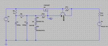
The first step of my proposed solution is to move the current limiter from the amplifier board to the regulator board and adjust it such that it limits the regulator output current to say 10A (see attachement). Since no energy is stored in the amp also the amp power devices are protected against overcurrent herewith.
Next I can insert a shunt relay in between the CReg and the amp. Since the shunt relay is shunting a voltage regulated but current limited source now shunting should be a save process without any damage risk for parts. I am even considering a solid state relay for shuning to get a clean shunt action instead of the nasty bouncing of mechanical relays.
Now the question is what to do with the C I have taken out for a moment.
Well there are serval options but I have to admit that I do not have a ready answer.
1) Maybe I could just leave it out here and add it to the first C -> CCReg.
This would be the easiest way but I am sure the designers had a good reason for this C. So I need to check the impact on SQ.
But if I would like to have the C back to the orignal position I need a current limiter for the C:
2) Connect a fast low current rated fuse link in series with the C. If I understand correcly the main purpose of the C is to help with a low output impedance for the CRegC but not for high current capability. And since during startup the C is loaded gently by the Reg softstart feature also during startup a low current fuse should work as well.
3) Are there any other options for a current limiter for the C ?
Patrick, I am almost sure you have one 🙂
Remarks and suggestions are appreciated.
Markus
But you should not blindly copy what I do.
You have enough options.
Patrick
Copy blindly is no fun 🙂.
(BTW, the 12V - 24V debate is no fun either, is this going to be the 12V - 24V relay thead?😕)
Here are my two pennies, a futher option for rearranging the F5X protection concept that I would like to throw into the game (Let´s mess up the original design a bit, that´s fun 😀) :
Let´s start with the design objectives:
1) The system shall provide speaker overvolt protection for the following error cases:
a) DC voltage provided by the line signal source or by connection error
b) Amplifier internal error, like defect devices and loose contacts and shorts
2) The system shall provide over-current protection for the following error case:
a) Overcurrent because of a short between amp and speaker
3) No relay contacts in the signal/power line
Although I did not made a thorough investigation of current depentend relay contact resistances I am pre-occupied enough now that I dicided that I would not like to have any relay contact in the signal path. In other words the best relays is no relays. Not even mercury wettet relays could beat that.
4) No current limiters on the amplifier board because the they become active very close to normal operation range ( >3A) and hence could give rise to signal distortion.
Now let´s assume for a moment the second 44,000 uF cap is out so we do not have a CRegC but just a CReg.
The first step of my proposed solution is to move the current limiter from the amplifier board to the regulator board and adjust it such that it limits the regulator output current to say 10A (see attachement). Since no energy is stored in the amp also the amp power devices are protected against overcurrent herewith.
Next I can insert a shunt relay in between the CReg and the amp. Since the shunt relay is shunting a voltage regulated but current limited source now shunting should be a save process without any damage risk for parts. I am even considering a solid state relay for shuning to get a clean shunt action instead of the nasty bouncing of mechanical relays.
Now the question is what to do with the C I have taken out for a moment.
Well there are serval options but I have to admit that I do not have a ready answer.
1) Maybe I could just leave it out here and add it to the first C -> CCReg.
This would be the easiest way but I am sure the designers had a good reason for this C. So I need to check the impact on SQ.
But if I would like to have the C back to the orignal position I need a current limiter for the C:
2) Connect a fast low current rated fuse link in series with the C. If I understand correcly the main purpose of the C is to help with a low output impedance for the CRegC but not for high current capability. And since during startup the C is loaded gently by the Reg softstart feature also during startup a low current fuse should work as well.
3) Are there any other options for a current limiter for the C ?
Patrick, I am almost sure you have one 🙂
Remarks and suggestions are appreciated.
Markus
Attachments
Last edited:
Andrew,
Patrick,
Do you know if there is a BOM here from Alexis for the original protection board?
Dave
Just a reminder - the protection board was not complete when I posted the amplifier and power supply build instructions. Alexis was still working on it then. I am not the author there and did not create any of the documentation.I have looked through all my saved F5x files and cannot find the Fitzfish BOM.
Patrick,
Do you know if there is a BOM here from Alexis for the original protection board?
Dave
Sorry Patrick,
Just noticed it is in the document you posted here.
Is this the latest version for the batch one protection boards?
Which BOM are you other builders using?
Dave
Just noticed it is in the document you posted here.
The promised circuit description of the protection board :
http://www.xen-audio.com/documents/f5x/130223 Protection Board F5X Chpt 1.pdf
Chapter 2 which is assembly & test is to follow.
This is delayed somewhat as Alexis has yet another hard disk failure.
So he lost a few days' work.
Patrick
Is this the latest version for the batch one protection boards?
Which BOM are you other builders using?
Dave
All regulators becomes inductive at HF, that is why you always see C's after regulators.
So for me no solution with CReg-no_C.
Current limiting follower regulators are plentiful around. You just need to google.
http://www.pmeweb.co.uk/Audio/psu.pdf
But they will cause current clipping in case the dynamic impedance of your speakers goes low (say < 1ohm) in a transient.
So I most certainly do not want one in my supply line either.
If you do not want to use a shunt relay at the amp output, then just use a relay to cut the CregC completely from the amp.
You immediately discard all stored energy.
The relay contact will see constant bias of >= 4A all the time during normal operation, so it is not likely to have inconsistent contact resistance.
And any noise caused by the contact can be filtered by a 1.5µF MKP, as I suggested in #805.
So thus far no better solution as the two I already described (shunt output or after CregC).
And I shall continue to use shunt speaker relays, as I have been for the last 10 years.
Patrick
- Home
- Amplifiers
- Pass Labs
- F5X -- the EUVL Approach - The Build Thread