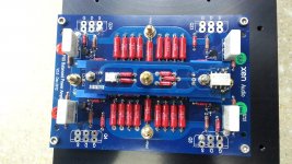
I found time today to troubleshoot and fix my protection and regulator boards, I now have CRegC up and running.
I also have a new pair of PMC twenty 22’s sounding particularly excellent.
Thanks to Patrick, Mark and Xen audio.
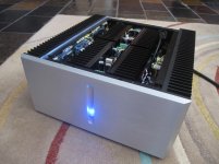
My finished amp... CRegC... Yeah Baby!
I also have a new pair of PMC twenty 22’s sounding particularly excellent.
Thanks to Patrick, Mark and Xen audio.
My finished amp... CRegC... Yeah Baby!
Attachments
Wowww... Congratulation johnwnclean 
As far I can see from your picture is a very clean build!
This week I will receive my box! Yeah... I can't wait more😀
Enrico
As far I can see from your picture is a very clean build!
This week I will receive my box! Yeah... I can't wait more😀
Enrico
> My finished amp... CRegC... Yeah Baby!
Firstly congratulations to John.
I would like to see :
a) a few more pictures of the internal layout and wiring
b) some temperature measurements on the heat sink, regulator sink, .... etc. vs. ambient
c) voltage and bias info after regulator
d) subjective descriptions if SQ.
Otherwise very well done. 😉
Patrick
I found time today to troubleshoot and fix my protection and regulator boards, I now have CRegC up and running.
I also have a new pair of PMC twenty 22’s sounding particularly excellent.
Thanks to Patrick, Mark and Xen audio.
My finished amp... CRegC... Yeah Baby!
Wow , what a sweeet build , what are the internal sinks for, Diodes ..?
> My finished amp... CRegC... Yeah Baby!
Firstly congratulations to John.
I would like to see :
a) a few more pictures of the internal layout and wiring
b) some temperature measurements on the heat sink, regulator sink, .... etc. vs. ambient
c) voltage and bias info after regulator
d) subjective descriptions if SQ.
Otherwise very well done. 😉
Patrick
No problem, I’ll get organised and post this up in the coming week.
Wow , what a sweeet build , what are the internal sinks for, Diodes ..?
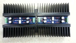
Rectifier diodes as well as the regulator MOSFETs.
OK, time to give some feedback:
I started this project end of 2010. Since then I got into a major earthquake, a nuclear disaster, a change of country and a new baby. I basically stopped any DIY since the beginning of 2012 due to extensive travelling, beside the minimal necessary to convert all my electronics from 100V to 230V. At one moment I thought I would never complete this and any other probject, at least for a while.
Anyway I put a quite some effort in it and many of you have at least some components of this built that passed by my desk, so in Christmas I decided to risk my marriage and complete the project (Actually jokig, as my wife was almost supportive). Being away for so long I was feeling kind of rusty and a bit lost, so apologize for the silly questions I asked.
If you think soldering SMD component is tricky, you should try to do it while a child is pulling your elbow 🙂
This to say that I have even more reasons to be happy. Now back to business for some electronics and I would like to give some, very personal tips to who is starting to build:
1) It is not strictly necessary, but if you have the possibility get the following tools: lab power supply able to do +-20 V 4A , a flexible screwdriver and a dummy load for the power supply a big magnifing lens with light. A varia would not hurt.
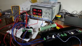
2) The audio part for me worked very well at the first try, although I put the bias a bit too high (The sound was good though). I started with 1.8 A with only the heatsink, but it claimbed to 2.2 A when everything was assembled. So I would aim for something like 300 mV drop on the 0.22 ohm resisistor. I found very VERY useful the tip given by Nic to assemble the audio board without the mosfet, connect the lab PSU and dial 2.15 V of GS. This gives you a much easier setup.
3) I did not use the dummy load but I should have had, as I have transformer with 16 V and not 15 V as prescribed. After some playing with the TL431 I decided to try my luck and installed a 22 V Zener, that gives me 16.0 V and 15.7V for positive and negative supply under load. The input of the regulators is around 18.5V.
4) I got a bit in trouble with the control board. I assembled everything in one go and this was a mistake. So I removed all the IC (I was confident that the other components were OK) and started from control and then adding one relay driver at a time. Like this I could check where the problem was step by step. At the end it worked. (Hopefully will continue to work). I had a silly problem with it that I will report as it took me some thinking to understand. I had one plastic washer of the to-220 device that got damaged, so that the chassis was at 12 V potential. This got undetected for one week, until I decided to complete everything and install the chassis grounding. After that it was happening that when I was connecting the DAC, if I was connecting only one channel (no matter which) everything was OK. If I was connecting both channels the DC protection was tripped. This was happening even with the amp in off state, so with input shorted. After scratching my head for a while I disconnected the earth from the chassis and I could measure 12 V: the problem was obviuos. I managed with a bit of patience and a tool I produced to unscrew the front panel without removing the PSU and fixed the condition. Now is everything as it should be. By the way, my protection board trips at 1.5 V.
I also got a bit in troubles with the mechanical assembly, partly due to the luck of connectors that is specific of my build, so follow the instructions.
I like the sound very much, I have a F5 with Toshiba outputs to compare with and the control and tightness improvement is easily detectable. I'll need to make some more listening when the ground floor of my flat is low, meaning everybody is out (Today's childern toys are a nightmare !!!)
I was thinking about deriving the wires from the push button and to have the preamlifier pushing the buttons for me. It would be easy to implement with a microprocessor.
About temperatures. This was another silly problem as my lab is in the wintergarden and it is consistently 5-6 degree colder than the living room, so I had to do some back and forward few time.
At 2.2 A and ambiet temperature 26 degree the main heatsinks were at 70 degree max 65 degree on the side. The regulator spot on the cover arounf 67. Now I have 63 degree max and 58 min, I think the bias is around 1.8A, but did not really measured it. I think that the grids below the amp really affect the dissipation of the regulator, so if the regulator is too hot you may leave the off. Also if you elevate a bit the amp, leaving more space between the heatsinks and the table, this will increase air circulation. Anyway I am kind of happy now, I will check again when summer comes. (At thet time my lab will be 10 degree hotter than the living room).
The DC offset is consistently below 1 mV.
Good listening to everybody !!!
Davide
I started this project end of 2010. Since then I got into a major earthquake, a nuclear disaster, a change of country and a new baby. I basically stopped any DIY since the beginning of 2012 due to extensive travelling, beside the minimal necessary to convert all my electronics from 100V to 230V. At one moment I thought I would never complete this and any other probject, at least for a while.
Anyway I put a quite some effort in it and many of you have at least some components of this built that passed by my desk, so in Christmas I decided to risk my marriage and complete the project (Actually jokig, as my wife was almost supportive). Being away for so long I was feeling kind of rusty and a bit lost, so apologize for the silly questions I asked.
If you think soldering SMD component is tricky, you should try to do it while a child is pulling your elbow 🙂
This to say that I have even more reasons to be happy. Now back to business for some electronics and I would like to give some, very personal tips to who is starting to build:
1) It is not strictly necessary, but if you have the possibility get the following tools: lab power supply able to do +-20 V 4A , a flexible screwdriver and a dummy load for the power supply a big magnifing lens with light. A varia would not hurt.
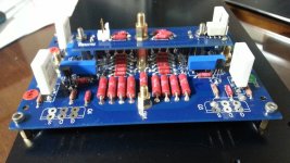
2) The audio part for me worked very well at the first try, although I put the bias a bit too high (The sound was good though). I started with 1.8 A with only the heatsink, but it claimbed to 2.2 A when everything was assembled. So I would aim for something like 300 mV drop on the 0.22 ohm resisistor. I found very VERY useful the tip given by Nic to assemble the audio board without the mosfet, connect the lab PSU and dial 2.15 V of GS. This gives you a much easier setup.
3) I did not use the dummy load but I should have had, as I have transformer with 16 V and not 15 V as prescribed. After some playing with the TL431 I decided to try my luck and installed a 22 V Zener, that gives me 16.0 V and 15.7V for positive and negative supply under load. The input of the regulators is around 18.5V.
4) I got a bit in trouble with the control board. I assembled everything in one go and this was a mistake. So I removed all the IC (I was confident that the other components were OK) and started from control and then adding one relay driver at a time. Like this I could check where the problem was step by step. At the end it worked. (Hopefully will continue to work). I had a silly problem with it that I will report as it took me some thinking to understand. I had one plastic washer of the to-220 device that got damaged, so that the chassis was at 12 V potential. This got undetected for one week, until I decided to complete everything and install the chassis grounding. After that it was happening that when I was connecting the DAC, if I was connecting only one channel (no matter which) everything was OK. If I was connecting both channels the DC protection was tripped. This was happening even with the amp in off state, so with input shorted. After scratching my head for a while I disconnected the earth from the chassis and I could measure 12 V: the problem was obviuos. I managed with a bit of patience and a tool I produced to unscrew the front panel without removing the PSU and fixed the condition. Now is everything as it should be. By the way, my protection board trips at 1.5 V.
I also got a bit in troubles with the mechanical assembly, partly due to the luck of connectors that is specific of my build, so follow the instructions.
I like the sound very much, I have a F5 with Toshiba outputs to compare with and the control and tightness improvement is easily detectable. I'll need to make some more listening when the ground floor of my flat is low, meaning everybody is out (Today's childern toys are a nightmare !!!)
I was thinking about deriving the wires from the push button and to have the preamlifier pushing the buttons for me. It would be easy to implement with a microprocessor.
About temperatures. This was another silly problem as my lab is in the wintergarden and it is consistently 5-6 degree colder than the living room, so I had to do some back and forward few time.
At 2.2 A and ambiet temperature 26 degree the main heatsinks were at 70 degree max 65 degree on the side. The regulator spot on the cover arounf 67. Now I have 63 degree max and 58 min, I think the bias is around 1.8A, but did not really measured it. I think that the grids below the amp really affect the dissipation of the regulator, so if the regulator is too hot you may leave the off. Also if you elevate a bit the amp, leaving more space between the heatsinks and the table, this will increase air circulation. Anyway I am kind of happy now, I will check again when summer comes. (At thet time my lab will be 10 degree hotter than the living room).
The DC offset is consistently below 1 mV.
Good listening to everybody !!!
Davide
Many congratulations. Glad you like the result, which is most important. 🙂
> I decided to try my luck and installed a 22 V Zener, that gives me 16.0 V and 15.7V for positive and negative supply under load.
> The input of the regulators is around 18.5V.
Then you are not regulating but just running as a cap multiplier.
You should at least have a drop of 3V across the regulator, and that gate of the MOSFET should be about 2.5~2.8V above the desired output.
If you study the circuit, you will also know that the gate voltage cannot be higher than the input voltage.
So if I were you I would use a 18V Zener, or lower.
And you should use an oscilloscope to look at the input, gate, and output of the regulator under load to satisfy yourself it is actually regulating.
Also simple enough to simulate in Spice.
MOSFET models were published (by someone else) here in the forum.
I was told by other builders that 1.6~1.8A will lower heatsink temperature without noticeable change in SQ.
So you may consider that also.
Patrick
Thanks,
This mistake was induced by NOT using the dummy load. I was expecting a much higher input voltage and I wanted to limit the voltage drop to avoid excessive dissipation. I was surprise as well when I found only 18.5 V in input (I was expecting something between 21-22 V) and I tested the circuit with the lab power supply and the F5X as a load with 21.5 V.
In theory it should not matter much regulation or multiplication at constant current, but I will "fix" it as the regulators are the only part that is easy to extract from the amp.
Regards,
Davide
One thing I forgot to say: the story about 12 V or 24 V relay is IMHO purely academic, at least for what concerns the signal relays. Looking at the specs the Omron relay is supposed to work between 75% and 200% of the prescribed voltage at 25 degree and between 75 % and 130 % at 75 degree. Additionallt it is stated a resistence of the coil 0f 1028 ohm. So as we have our remperature is around 60 degree, even if we use the 75 degree parameters we have a voltage range between 9V and 15.6 V. If you just with a 1k resistors on the cable your 12 V relay will always be operated in a safe spot. The resistor will dissipate 0.1 w. So I have 12 V relay and I did not bother to complicate the wiring and connect them in series.
If you have different relay check the specs of what you have in term of coil resistance. Basically you need the same value to divide the voltage by two.
Have a nice build,
Davide
If you have different relay check the specs of what you have in term of coil resistance. Basically you need the same value to divide the voltage by two.
Have a nice build,
Davide
For what it's worth, I had my 12V input relays wired separately (seeing 24V) and I used them this way for many listening hours without a problem. I did install resistors last weekend just to be safe and to make sure I don't have any long term problems.
CregC Test
I am quite sure that the answer is already somewhere in the thread but I can't find it.
I have complete the CRegC circuit but I still waiting the trasformers from Toroidy.
Today I make some tests with a lab PSU give as Vin 21V (16V x 1.3), the caps for the input and the output with a load of 4ohm 100W (the only one that I have) and those the results for the 4 Vout tested one by time:
R channel: + Vout 15.23 / - Vout 15.32
L channel: + Vout 15.40 / - Vout 15.23
I was expecting something more near to 16V 😕
I see also that in the BOM is listed the 1N4001 in series with the Zener but looking in the thread Patrick talk about 1N4148. Which is the correct one?
Thanks
Enrico
PS: almost forget to say... the 1N4001 is not SMD (still waiting the box from Mouser) and temporary I put a normal one
There is no current in the diode, so any normal silicon diode will do, both 1N4148 and 1N4001.
If you want to raise voltage by 0.8 ~1V then replace the 1N4148 with a red LED.
And you should measure and hand pick your Zener, as they vary quite a lot.
Patrick
If you want to raise voltage by 0.8 ~1V then replace the 1N4148 with a red LED.
And you should measure and hand pick your Zener, as they vary quite a lot.
Patrick
Work in progress
Some update of my work in progress...
CRegC - I change the diode with the LED as suggested by Patrick and voila'!... Now I have 16,3 to 16,5 Volts in all the 4 regulators... thanks Patrick 😉.
Amplifier - 1 channel completed last night with the exception of the Mosfet... was also the first time in my life that I solded the SMD... a little panic but was not so terrible as I was thinking. This make me more confident for the protection pcb. I power up with the lab psu (no smoke...yeaa) and I have the following Vdrop on the 4 11ohm:
R1=52.0mV, R21=51.9, R2=53.4 and R22=53.5
I trim back also the Vgs of the 4 mosfets at 2.3V
My plan now is to complete the second amplifier and bias (I hope) as the first and waiting for the transformers that next week should be shipped.
When I have the transformers I will complete the PSU, make the initial bias based on the final PSU.
Last one will be the protection board
Regards,
Enrico
Attachments
Just thought I’d mention...
I applied a little loctite to the brass standoff threads for the amp boards.
Once everything is bolted down, you don’t want these to loosen...
I applied a little loctite to the brass standoff threads for the amp boards.
Once everything is bolted down, you don’t want these to loosen...
Your welcome Enrico,
Heres a set of photos of my F5X as a work progress.
Kind of weird but I started with the protection board first, then the amp boards and finally the PSU. Anyways the photos tell the story... this is unedited and has many repeats of similar images.
https://www.flickr.com/photos/82163546@N06/sets/72157640966440133/
Hi John,
If you start from the protection board you are more brave then me... every time I think that I have to play with all this microscopic SMD I scare and I postpone😱
Very nice photoshop indeed... I enjoy it!
I have noticed that you have taken care of all the details. If you don't mind I will give a look sometimes during my building 😉.
Cheers,
Enrico
> I applied a little loctite to the brass standoff threads for the amp boards.
Loctitte is not electrically conductive ??
> Once everything is bolted down, you don’t want these to loosen...
For those with eletrical connections (outputs, supplies, ....) I solder them to th board with a high power soldering iron (min 100W, preferrably 200W).
Patrick
Loctitte is not electrically conductive ??
> Once everything is bolted down, you don’t want these to loosen...
For those with eletrical connections (outputs, supplies, ....) I solder them to th board with a high power soldering iron (min 100W, preferrably 200W).
Patrick
- Home
- Amplifiers
- Pass Labs
- F5X -- the EUVL Approach - The Build Thread