Now I get what the fuss is about Nelson Pass' amps...
I've built a F5 turbo V2 and absolutely love it! I thought my VTA - ST70 tube amp was really great, but the F5 turbo is noticeably better. Even the wife heard the difference!
A special thanks to 6L6 and his great build guide and email support!
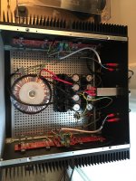
I used a 800va toroid, the V3 boards, the 5u Deluxe chassis. It fired up without any issues. Initial bias setting is about 375mv with 47 degrees centigrade temperature at the heatsink.
Some pictures attached (it is the big box on the top right of the rig 😀 ).
More on my blog: https://zimmer64.wordpress.com/2016/10/23/pass-f5-turbo-v2/
Cheers
Michael
I've built a F5 turbo V2 and absolutely love it! I thought my VTA - ST70 tube amp was really great, but the F5 turbo is noticeably better. Even the wife heard the difference!
A special thanks to 6L6 and his great build guide and email support!
I used a 800va toroid, the V3 boards, the 5u Deluxe chassis. It fired up without any issues. Initial bias setting is about 375mv with 47 degrees centigrade temperature at the heatsink.
Some pictures attached (it is the big box on the top right of the rig 😀 ).
More on my blog: https://zimmer64.wordpress.com/2016/10/23/pass-f5-turbo-v2/
Cheers
Michael
Attachments

Great build! Thanks for the pictures to motivate me. I like your paintings aswell!
Can't take credit for the paintings. They are my wife's work 😎 Will tell her you like them.
I had set up a workbench in her atelier for this project. I installed my open baffle speakers there. The sound of those is addictive and one is surrounded by all the artwork.
Great setting for listening to music, surrounded by your wife's art work! My wife paints and does print work.
Ok, I got rid of the earth bridge rectifier thing as it lead to sparkling fun and ommitted as well the thermistors....already a very audible step into the right direction. Clearer imaging while maintaing the nice warm signature. Next weekend then conversion back to v1...
Straight connection between ground, earth and chassis. If I am thinking how serious we took the question in which direct the power plug has tobe...maybe the bridge is not so great to help the current flow between pre and power which goes on over the power plug(smal, but audible therefore the starground scheme in some powerdistribution)
Guys quick one.. need to check of I can replace MUR3020W (Dual 200V 30A Common Cathode) with MUR3060 600V 30A UltraFast Rectifiers (Dual 600V 30A Common Cathode) for F5-T v3's
they are both common cathode and your replacement is rated higher for both voltage and current.
Is the Vf similar to the original?
Then if it fits the space and pads it should work OK.
Is the Vf similar to the original?
Then if it fits the space and pads it should work OK.
MUR3020W Vf 1.05V at 15A in TO-247, MUR3060W Vf 1.7V at 15A in TO-247
Sent from my iPhone using Tapatalk Pro
Sent from my iPhone using Tapatalk Pro
That's a big difference. If it really is that different then it may change the performance of the circuit.
Humm...fair enough, I had almost 16 in stock, thought I would use them for F5Tv3
Sent from my iPhone using Tapatalk Pro
Sent from my iPhone using Tapatalk Pro
I may sound stupid but why you can't fit a stereo F5T v3 in an 5U chassis?
From the schematic I see 8 output transistors. But you guys are using 16 transistors in mono-block configuration. I don't understand. Can someone clarify for me, thanks.
From the schematic I see 8 output transistors. But you guys are using 16 transistors in mono-block configuration. I don't understand. Can someone clarify for me, thanks.
It's not the size of the chassis, it's the size of the heat sinks. I'm working on a pair of F5Tv3 monos (4 pairs per ch) in the 5U chassis' from the DIYAudio store (only one finished so far 🙁 ). At 350 ma bias it runs 48-50* C. They require a LOT of heat sinking!
TJ
TJ
I am still confused. Is this guide for F5T v2? The schematic shows F5T v3 and the pcbs have 8 output transistors like V3. How many pcbs from DIY store for a stereo F5T v3?
Salvaged very nice danish transformer from dantax amp. Unfortunately it has 2*32v secondaries. Is it possible to use this one for V2? Looks like rating is 600va.
v 2.2 boards
with this version of the front end do you still have to jumper q7 and q8, when not cascading, previous front end was q5 and six, when I say this version it refers to version 2.2
with this version of the front end do you still have to jumper q7 and q8, when not cascading, previous front end was q5 and six, when I say this version it refers to version 2.2
Last edited:
Post1 sch shows Q7 & Q8 as the cascode transistors.
A quick scan down the long post did not reveal a change from that.
A quick scan down the long post did not reveal a change from that.
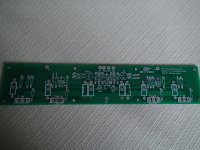
I have built more than twenty F5V2 steroset, but never run into a problem like this. PCB is cvillers(see photo).
Setting bias give this results on sourceresistors: Q4(NPN) 254 mV but on Q 104(second NPN) 11.4 mV. Q3(PNP) 240mV but on Q 103(second PNP) 28.5 mV. Offset is no promlem to adjust(1-2 mV).
I have other NPN and PNP taken from the same bat. so to find two of each to match will be easy(but not matching NPN and PNP). As long as I can adjust offset close to zero, I find this kind of matching fair.
Any good advices??
Attachments
- Home
- Amplifiers
- Pass Labs
- F5Turbo Illustrated Build Guide