This what I have done so far:
Measuring sourceresistance:
On NPN side: 0.4633 and 0.4674. PNP side: 0.4661 and 0.4674. O.K I suppose.
I have used a testrigg with 2.2 kohm(1%) connected to Sorce. Gate and Drain shorted. Drain connected to "earth" and the "free" end of 2.2kohm to 15 V. I have taken the measurement between Source and Drain. I have not have time to test FETs in my F5V2 decriebed in #320. But i picked out three NPN and PNP newly bought from Farnell.
9240 240
0.993V 0.555V
0.995V 0.558V
0.987 0.555V
I also measured some "old " 9240 and I got this results:
1.200V
1.189V
1.197V
0.562V
0.686V
0.559V
Have I done the right measurement??
Eivind S
Volts, Amperes or ohms?On NPN side: 0.4633 and 0.4674. PNP side: 0.4661 and 0.4674. O.K I suppose.
Pchannel slightly higher than Nchannel is typical.9240 240
0.993V 0.555V
0.995V 0.558V
0.987 0.555V
But for a Vertical mosFET the Vgs (if that is what you have posted) are far too low.
I'd expect 2V to 4V for Vgs when the transistors are passing.
Last edited:
Measuring sourceresistance:
On NPN side: 0.4633 and 0.4674. PNP side: 0.4661 and 0.4674. O.K I suppose.
Resistance in ohm, of course.
I have used a testrigg with 2.2 kohm(1%) connected to Sorce. Gate and Drain shorted. Drain connected to "earth" and the "free" end of 2.2kohm to 15 V. I have taken the measurement between Source and Drain.
The low values on vgs might have connection to the 2.2 kohm I have used. I have seen both 100 ohm and even as low as 56 ohm (2W and FET connected to a heatsink) instead of the 2.2 kohm. Can this have influenced on the low vgs I have measured. Will 100 or 56 ohm bring me closer to 2-4 volt?
Eivind S
I don't know how you are able to measure 0r4633 with that resolution?
I don't have any clue why you are adding that jig to measure Vgs?
I don't have any clue why you are adding that jig to measure Vgs?
I'd guess a 6 digit bench DMM.
I don't know how you are able to measure 0r4633 with that resolution?
"I don't have any clue why you are adding that jig to measure Vgs?"
I found this:http://www.diyaudio.com/forums/solid-state/299546-nelson-pass-easy-peasy-mosfet-vgs-measurement.html
"I don't know how you are able to measure 0r4633 with that resolution?"
DATS V2
Eivind S
I found this:http://www.diyaudio.com/forums/solid-state/299546-nelson-pass-easy-peasy-mosfet-vgs-measurement.html
"I don't know how you are able to measure 0r4633 with that resolution?"
DATS V2
Eivind S
hi guys,
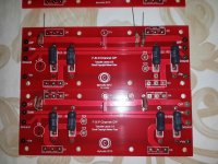
I stuffed FE boards in my spare time following 6L6's perfect build guide.
I could not set P3 trimmers to exact value (which is 100 ohm), one of them set as 101.2 ohm and the other is 108.2 ohm (from leg 1 to 2 and 2 to 3)
is it okey?
and another question is that
I also stuffed but not soldered n channel and p channel boards, I have some missing items which are C1x and C2x, I need 4 10uF electrolytic cap, but I have 2.
They are strictly necessary or should I leave them empty?
because according to 6L6's built guide, they seem empty on some photos.
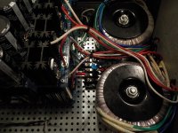
Please see the attached pics.
I stuffed FE boards in my spare time following 6L6's perfect build guide.
I could not set P3 trimmers to exact value (which is 100 ohm), one of them set as 101.2 ohm and the other is 108.2 ohm (from leg 1 to 2 and 2 to 3)
is it okey?
and another question is that
I also stuffed but not soldered n channel and p channel boards, I have some missing items which are C1x and C2x, I need 4 10uF electrolytic cap, but I have 2.
They are strictly necessary or should I leave them empty?
because according to 6L6's built guide, they seem empty on some photos.
Please see the attached pics.
Attachments

F5T V2 running, have a fewe of q's to finish settings.
Hello all. Thank you for all the resources I am happy to report that I have completed building the amplifier, I'm new to the forum and this is my first day project. I wasn't hesitant to do it until a fellow member decided to sell an incomplete kit.
Build when fairly well. Lots of time spent, learned a lot. Thank you for all the insight and advice find in the board.
Here are the q's.
.I'm using the 5u deluxe chassis, dual transformers at 300VA each, dual power supplies each channel gets its own+/-, rails are at +/- 40 volts using the PS3 boards and 60,000 uF of filtering per power supply side for a total of 240,000 uF. Bias set at 350 mV and 360 mV across source resistor. Output dissipation estimated just below 30 Watts per device. Differential temperature between room and heatsinks is 25 degrees Celsius. Room at 17 degrees, heatsink at 42 degrees.
1. How close am I to the limit of the chassis dissipation capability?
2. How to figure case temperature of the output devices? In have infrared thermometer?
3. How do I figure the maximal output, I have 8r dummy resistor 500w available and a function generator?
4. How important to balance gain between channels?
5. Practical way to adjust p3 if audio analyzer is not available?
6. Unrelated. I'm feeding the amp with a mesmerized B1 buffer without chassis ground is floating. I get a ground loop when connected, amp is dead quiet so it's the buffer. What is the proper way to ground the B1 beard?
Thank you again for everything.
If your summer temperature went up to 30degrees C (no air con), then your sink would be @ 55degrees C. This is OK.Hello all. Thank you for all the resources I am happy to report that I have completed building the amplifier, I'm new to the forum and this is my first day project. I wasn't hesitant to do it until a fellow member decided to sell an incomplete kit.
Build when fairly well. Lots of time spent, learned a lot. Thank you for all the insight and advice find in the board.
Here are the q's.
.I'm using the 5u deluxe chassis, dual transformers at 300VA each, dual power supplies each channel gets its own+/-, rails are at +/- 40 volts using the PS3 boards and 60,000 uF of filtering per power supply side for a total of 240,000 uF. Bias set at 350 mV and 360 mV across source resistor. Output dissipation estimated just below 30 Watts per device. Differential temperature between room and heatsinks is 25 degrees Celsius. Room at 17 degrees, heatsink at 42 degrees.
You are getting close to chassis/sink limit if your max Ta is around 30degreesC.1. How close am I to the limit of the chassis dissipation capability?
If you predict rather than measure the impossible, you will get closer. For an Rth c-s of 1C/W and 30W passing across the insulator, then Tc=Ts+1C/W*30C2. How to figure case temperature of the output devices? In have infrared thermometer?
If you use a much more thermally conductive insulator say 0.3C/W, then Tc = Ts + 0.3C/W*30C
This better insulator allows the devices to operate 21C degrees cooler.
Don't figure it out. Measure it.3. How do I figure the maximal output, I have 8r dummy resistor 500w available and a function generator?
You need a scope to monitor the highest available output voltage without any sign of clipping of that signal when the load is connected. You need a fairly clean signal source <0.5% sine distortion is probably good enough.
You need an AC voltmeter that reads to better than +-1%.
You need some form of switching arrangement to prevent overheating while you take the measurements and monitor the non clipping, while driving enormous current into your dummy load.
Pmax = Vac^2 / Rload
Not important. +-5% resistors (gold stripe) give a worst case error of +10% and -10% between the channels and that accounts for only 1.7dB between the channels. You can check your resistors with your ohms function on your DMM and get channel matching to much better than +-1%, giving <<0.5dB between channels.4. How important to balance gain between channels?
Don't adjust p3. Set it exactly to electrical middle. And leave it there. Don't try to fiddle by ear. Ears+brain are terrible at measuring.5. Practical way to adjust p3 if audio analyzer is not available?
It's probably not the Buffer.6. Unrelated. I'm feeding the amp with a mesmerized B1 buffer without chassis ground is floating. I get a ground loop when connected, amp is dead quiet so it's the buffer. What is the proper way to ground the B1 beard?
Thank you again for everything.
Read D.Joffe and install HBRR+HBRL
Last edited:
F5T V2 running, have a fewe of q's to finish settings.
Read D.Joffe and install HBRR+HBRL[/QUOTE]
Thank you Andrew, I appreciate the time you took to reply. I have read a lot of your postings because they have a lot of useful technical details.
Pardon my ignorance, who is D Joffe and what HBRR and HBRL stands for? I have searched and came empty. Thank you!
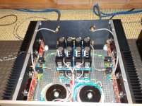
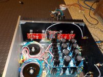
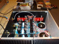
F5T V2 Pictures
Inspired by of all of you, I purchased an unfinished kit from fellow board member in Utah with most of the parts for V3 monoblocks. Thank you!. I did not have the time and skills to engineer my own chassis so I used the 5U from the store. Once I received the chassis and realized how big they are, I decided to build a V2 with dual power supplies instead. So here it is. Standard build following Jim's guide.
Inspired by of all of you, I purchased an unfinished kit from fellow board member in Utah with most of the parts for V3 monoblocks. Thank you!. I did not have the time and skills to engineer my own chassis so I used the 5U from the store. Once I received the chassis and realized how big they are, I decided to build a V2 with dual power supplies instead. So here it is. Standard build following Jim's guide.
Attachments


F5T V2 ground loop
It's probably not the Buffer.
Read D.Joffe and install HBRR+HBRL[/QUOTE]
Andrew, I found it: Ground Loop again
Post # 22.
Thanks.
It's probably not the Buffer.
Read D.Joffe and install HBRR+HBRL[/QUOTE]
Andrew, I found it: Ground Loop again
Post # 22.
Thanks.
Class A
this is my first class a build, I have the amp about ready to fire up, I have the pots set to zero, my question is the fets are reading 96 ohms, is this normal for class a? on ab 400 to 500 is normal is why I ask
this is my first class a build, I have the amp about ready to fire up, I have the pots set to zero, my question is the fets are reading 96 ohms, is this normal for class a? on ab 400 to 500 is normal is why I ask
ever found anything about JFets matching ?
if in doubt , test
and , always be precise when typing ; only you know for sure what you are actually thinking ........ others can just guess , more or less
if in doubt , test
and , always be precise when typing ; only you know for sure what you are actually thinking ........ others can just guess , more or less
Sorry was late last night, when I test the legs of the transistors after installing the jumpers as explained if not cascading, I am getting readings of 96 ohms across the legs of the 9240's
I would recommend to double check your work, if all is looks ok, follow Jim's (6l6) procedure to turn it on using a Variac or the Light bulb cord. One channel with be conducting a little (P-channel I think), the other will be off but it will come alive as you start adjusting the bias potentiometers. Measuring resistance will not give you a certain answer if the amp is ok. Good luck.
Newbie Question speaker output
On the f 5 turbo where do you hook the speaker outputs to? I assume ve- and op but not sure, please help lol
On the f 5 turbo where do you hook the speaker outputs to? I assume ve- and op but not sure, please help lol
- Home
- Amplifiers
- Pass Labs
- F5Turbo Illustrated Build Guide