Hello dpogorman,
nice projects you did! Absolutely no laughing from my side. More a kind of respect. 😉
Cheers
Dirk 🙂
nice projects you did! Absolutely no laughing from my side. More a kind of respect. 😉
Cheers
Dirk 🙂
Hello,
I have implemented the input (FE) board with an additional board to convert the input signal from balanced to unbalanced, I used a schematic I found on youtube, as an op-amp for the realignment of the inverted signal I used the Ti LM741 (one per channel), attached is the circuit diagram,
(requires dual +- 9V or +- 12V power supply)
I am currently testing it externally to the power amp and I must say it sounds really good, I think I will install it inside the power amp.
Attachments

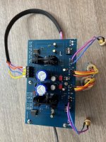

Tricksters, that is a nice input circuit! A differential amplifier. Question: the PCB has a few caps more, and a semiconductor device on a heat sink, which do not seem to be in the schematics. What are those? I am especially curious about the semiconductor device. Is that an output buffer, like an emitter follower?
All-in-one powe supply and active converter,
dual +-12V DC stabilised power supply, with LM7812 and LM7912.
dual +-12V DC stabilised power supply, with LM7812 and LM7912.
The circuit is not mine, I got it from youtube,
other clarifications can be requested
"https://wwwdotyoutubedotcom/watch?v=STsvWLTLkn0"
other clarifications can be requested
"https://wwwdotyoutubedotcom/watch?v=STsvWLTLkn0"
Why not try Nelson's front end circuit. https://www.diyaudio.com/community/threads/diy-front-end-2022.394339/
Thanks Eslheadphone! Forgot about that one. The schematics are easy to read: a long tailed pair and a class A second stage. Beautiful! And probably much less noisy than the staple 741 opamp. Will order a set from the store and build it. I might go for a 0 dB gain, because my F5T already has enough gain: I just want to add the option of having balanced inputs. Or I might replace the 100 k feedback resistors with an Alps potmeter, and then have variable gain.
Hello,
I wanted to do some routine checks on the F5-Turbo power amp, and to my amazement I saw that the multimeter couldn't read the offset values on the left channel of the power amp correctly, it was oscillating continuously in a range between -65mv and +35mv, I reset the trimpot values on the FE board and re-calibrated the bias to values around 300mv (I can't get them any higher), but the multimeter couldn't read the offset correctly, it always reads values between -50-60mv and +30-35mv.
I measured the AC voltage at the output terminals of the left channel and the multimeter reads a stable AC voltage of 10V, while on the right channel the bias and offset values are within the normal range.
I don't understand what could have happened.
What do you think?
What is the source of the problem?
What do you think?
What is the source of the problem?
Here is what 6L6 says about oscilation in his most excellent build guide for the f5t v2/3. I used 470 ohm gate resistors on my build.
"Also, in my opinion, C3 and C4, labeled here as ‘OPT’, are required for stability from destructive oscillation. This is a very high bandwidth design and those caps help protect it from ultrasonic HF oscillation. Use 1000pF. Also, if oscillation is a problem for your build, increase the value of the gate resistors (R13 -16 and similar) any value from 47.5R to 680R will work and sound fine, the higher the value the more damping occurs."
I checked the P-ch and N-ch boards, the capacitors
c3-c4 are there and have a value of 1nF, so OK, while resistors R13-R16 are 47.5 Ohm, I will replace them with 1/2W 470 Ohm, following your advice, resistor R11 2k2 ohm is not present, I will also install this.
I hope to solve the problem.
Of course I will also perform the same operations on the other right channel.
Thank you.
I’m going to be redoing my F5Tv2 converting to monoblock v3’s. Is the general consensus to NOT use the diodes? I removed them from the v2 based on many of the threads I read but it also there seem to be a lot of builds using them. Thoughts?
I took the diodes out a year ago. It made the amp much more stable, especially for higher biases. Been a happy F5T V2 user ever since. If you go to V3, you probably do that for having more available current for driving low impedances? As far as my limited electronics knowledge can tell me, the diodes reduce the voltage over the source resistors when the current really goes up, so a little more rail voltage is available. for me that advantage was not worth the risk of more instability. Coukd be that I am totally wrong though...
The best way to use the diode is to lower the 0.5 ohm source resistance to about 0.33 or 0.25 (adding more 1 ohm resistors in parallel should do it). This allows higher bias while allowing you to keep the diodes, at the cost of some OLG and worsening the objective performance a bit.
@Gerrit Kroesen Yes, that is a good analysis. And I agree with @Sangram work-around as a good idea.
I think the diode issue stems from the manufacture of the MUR3020W… when Nelson designed the F5T, the part was made by Vishay, and it had a very specific temperature/current/resistance curve. OnSemi also makes them, and for a time were the only ones available… and perhaps they have a different curve and they make the amp more unstable? This is conjecture, I do not have solid evidence of this.
The easiest thing is just omit the diodes altogether and build the amp. The absolute peak power may not be quite as high, but you amp will still make lots of power and more importantly, be significantly more stable.
Thank you guys! I have one more question. Do to the weight of the 5U case itself along with an 800 VA transformer, caps, etc gets to be pretty heavy for an old fart like myself. Whats are the thoughts of having remote psu’s in a smaller lighter case connected to the main amp 5U chassis by an umbilical cord or such? Is that possible and if so, is it best to send over the rail voltage after the rectifiers or the low voltage AC then rectify and filter it in the 5U chassis? Am I inviting troubles or do I run any risk in doing so?
This is something I have considered many times, but never did. Nelson Pass has sometimes suggested to place the psu in a seperate frame elsewhere in the forum. Advantage is also that you get rid of the transformer EMC problems. Personally, I would then rectify and filter in the seperate chassis, so that the umbilical only has DC, and the AC entering the amp box is the ripple on the rail voltage.
- Home
- Amplifiers
- Pass Labs
- F5Turbo Illustrated Build Guide