I forgot to add, these are Balanced F5t v3, the 2 FE boards are connected together using the "link", white wire.
I am in need of advise, I'm currently attempting to adjust bias and DC offset on my Mono block F5t v3. I have separate power supplies for each channel, my first attempt resulted in a very burnt Q3 where the Gate pin dissolved off the MOSFET.
I have 51vdc on the rails under no load, when I was adjusting bias the first time, the rail voltage was a very steady 48.1vdc with 200 mV of bias. My heat sinks are 10" wide X 14" tall with a 10mm base and 2" fins.
Each channel has two FE boards, 2 P channel boards, and 2 N channel boards. I have tested both mono blocks using the dim bulb tester and everything is good even with the output boards connected.
How do I measure DC offset? My first attempt, I had the DVM connected to each (+) & (-) output leads to the speaker terminals. No matter what adjustment I made, no noticeable difference was noted on the DVM for DC offset.
My other channel mono block is ready for adjustments and I am VERY unsure as to how to continue.
Should I measure DC offset for (+) to ground and adjust that FE boards P1 & P2?
Then do I measure (-) to ground and adjust the other FE board P1 & P2?
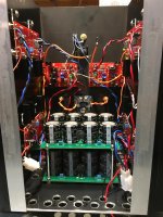
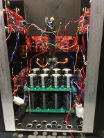
Here is a photo: Orange wires are OP, Red V+, Blue V-, Black is ground, Yellow is P channel gate and Purple is N channel gate.
I am a total novice here so I’m not positive but I thought I read in one of these threads on a F5Tv3 mono-block you only use 1 fe board but I’d wait until the senior guys jump in here.
Yes, 1 FE board for single ended mono blocks, I'm building Balanced mono blocks which use 2 FE boards. After typing before, I think I should treat the (+) and (-) as 2 separate channels. One FE board with one P channel and one N channel and measure between output and ground for each. Just not sure if the "link" should be connected or disconnected during the adjustments.
Measuring DC offset between output and ground made a difference. I was able to adjust bias with P1 and DC offset adjustment with P2, finally able to make a difference with DC offset.
Now my problem is P channel has almost twice the bias as N channel. I had 320mV on the P channel and only 180 - 190mV on N channel.
When I measure resistance between TP2 and TP3, I measured 0.9 ohms on N channel and 0.5 ohms on P channel. All the output boards have 1.0 ohm DALE RW79U resistors.
Now my problem is P channel has almost twice the bias as N channel. I had 320mV on the P channel and only 180 - 190mV on N channel.
When I measure resistance between TP2 and TP3, I measured 0.9 ohms on N channel and 0.5 ohms on P channel. All the output boards have 1.0 ohm DALE RW79U resistors.
Elwood, I would think having to measure offset to ground, means something might be connected wrong.
Is there DC offset between + and - outputs? Will you connect speaker wires to those two points? If so and it is significant, you will fry your speakers.
Just a thought.
I don’t have time to look into the bias issue, but someone else will chime in on that.
Regards,
Andy
Is there DC offset between + and - outputs? Will you connect speaker wires to those two points? If so and it is significant, you will fry your speakers.
Just a thought.
I don’t have time to look into the bias issue, but someone else will chime in on that.
Regards,
Andy
Last edited:
Correction: offset should be measured towards gnd, what beats me is why your speaker neg is not connected to a place where offset can be zeroed.
Hello gang, I’m not sure but may be in trouble again. Last week the mounting washer on the output board shorted to the o/p line. I knew at least one of the N channel MOSFETS were smoked. ItsAllInMyHead Patrick came to the rescue. He bailed me out sending not only a pair of N channel MOSFETS but also a set of P channel as well which it turned out were also smoked. So both N & P MOSFETS are changed. So bringing the power up very slowly through the variac AND going through the dimbulb, I am seeing resistors R7-R10 getting pretty hot, about 62C/143F. i shut off the amp prior to smoking anything and came to the forum for some direction. I don’t this is normal. I checked my other channel and they didn’t even get warm. I did turn pots p1 & p2 down to their minimum positions prior to powering up. Any thoughts please and thank you in advance. Joe
Correction: offset should be measured towards gnd, what beats me is why your speaker neg is not connected to a place where offset can be zeroed.
I had no problem adjusting DC offset to zero. My concern is the difference in bias from P channel to N channel,
There are a three offsets we can consider here:
1) OUT+ to GND
2) OUT- to GND
3) OUT+ to OUT-
The first 2 are absolute offsets. The last is relative offset and is what your speaker
sees.
What dc offset is zero?
Please note that the relative offset can be zero without the absolute offsets being zero.
Conversely you can have both absolute offsets zero without the relative offset zero.
Hi Dennis -
I was adjusting OUT -, for once I was able to make an adjustment and have the DVM for DC offset respond. I was able to adjust to zero after every small bias adjust.
I'm going to set OUT- to around 275mV with DC offset s close to zero, then adjust OUT+ to 250 - 275mV and then let it cook for an hour and see.
I hope that after getting both phases close and I measure relative offset, I'm close to under 50mV.
Hello gang, I’m not sure but may be in trouble again. Last week the mounting washer on the output board shorted to the o/p line. I knew at least one of the N channel MOSFETS were smoked. ItsAllInMyHead Patrick came to the rescue. He bailed me out sending not only a pair of N channel MOSFETS but also a set of P channel as well which it turned out were also smoked. So both N & P MOSFETS are changed. So bringing the power up very slowly through the variac AND going through the dimbulb, I am seeing resistors R7-R10 getting pretty hot, about 62C/143F. i shut off the amp prior to smoking anything and came to the forum for some direction. I don’t this is normal. I checked my other channel and they didn’t even get warm. I did turn pots p1 & p2 down to their minimum positions prior to powering up. Any thoughts please and thank you in advance. Joe
I’d like to add a couple things. I’m measuring 23 volts across resistors R7-R10 on the trouble channel and about .3 volts on the good channel. Across R25 & R26 on trouble channel 19.3 volts and on operating channel 10.3 volts. ?
Last edited:
luvrockin - I'm a Mechanical Engineer not an Electrical Engineer, so my knowledge on this subject is limited so all I can do is quote Nelson.
R7 - R10 are the feedback resistors, they are big for a reason, they feed the output back to the JFET's on the input to reduce THD.
In the example of cascode Q7, a voltage reference is set by resistors R25and R27 between V+ and Ground so that the Jfets see about 1/3 of the rail voltage.
Are you using the diodes with the source resistors?
First thing I would do is check my work, look at the MOSFETS again, beware of washers unless they are lock washers.
Next, because your cascode reference voltage is high, test your JFETS.
I must admit, I have a new respect for this amp.
Elwood625, Thank you for the reply. I’m not an electrical engineer either. I’m just an hvac who enjoy dabbling with this stuff. Unfortunately this one is a little intense. I am using the source resistors with diodes. I can pull the jfets tomorrow and test them. Is there a way to test them in the circuit. As I’m sure you know, it’s a pia pulling parts from these boards. You mention beware of the washers. What happens with the washers?
Since you have a good circuit to work with, I would test using the diode tester on the DVM, look for an open circuit, if you have doubt test the other side and compare. Do the same with the diodes, and look at the source resistors. Since the MOSFETS had over current damage, see if they are OK, the source resistors and diodes flowed all that current through the MOSFETS. If the markings on the resistor look good, once again a compare test should work. Fried resistors usually mean open circuit or close to it and fail the visual inspection. If in doubt, throw it out. Old saying from racing days, don't forget the 12 Hours of Sebring starts tomorrow morning, watch the start on NBC and then go play with the amp.
Next time you may want to go the route I use, spark, flame, smoke. Easy to diagnose.
Next time you may want to go the route I use, spark, flame, smoke. Easy to diagnose.
Regarding washers, steel washers make a wonderful conductor of large amounts of current, not so good at heat dissipation. If you look at the data sheet for MOSFETs, data sheet is operation manual, there is no discussion of mounting instructions.
I use small alloy heat sinks to retain the MOSFETs and just the 3mm mounting bolt of the diodes. The only reason I used the heat sinks was all the discussion about heat.
I use small alloy heat sinks to retain the MOSFETs and just the 3mm mounting bolt of the diodes. The only reason I used the heat sinks was all the discussion about heat.
- Home
- Amplifiers
- Pass Labs
- F5Turbo Illustrated Build Guide