Dennis, thank you as always for your thorough and easy-to-understand explanations!
I tried to follow along, but as usual... questions emerged. I think I worked through it enough to understand the circuit and the thermistor's functionality along with the power-handling requirements for the thermsitor.
I ran three scenarios at 20C, 45C (per above), and a WOW! temp of 75C.
R = 5802, 2502, and 694 respectively per the datasheet.
I=8/(2210+2502) => 2.76mA
I^2 * R <=> (64*2502)/((2210+2502)^2)
7.212mW
The math jives both ways.
Where my brain melted even under low heat was when doing the same calcs for the lower and higher temps, I got lower power at both. 5.8mW at 20C and 5.3mW at 75C.
Before posting my original though / question, I assumed incorrectly that the lower resistance of the thermistor as it got hotter would directly correlate to more current => more power. Then... I realized after going through your posts and doing a few scenarios, that DUH! P=I^2*R and the resistance lowers as the temp increases. The fact that the power through the thermistor is still lower at 75C is due to the non-linearity of the resistance change.
Oh well, that'll now stick in my brain. 😀 A person more dedicated than I could do some math along with reviewing the tables to determine the temperature at which maximum power flows through the thermistor. However, knowing where we are within these "normal" operating temps is comfort enough for me.
Heat still scares me. 😀
Heat still scares me. 😀
Hah! No it doesn't. You build Burning Amps!. 😀😀😀
In the approximation above, the max occurs at R=2210. Going by
the thermistor datasheet, that should be at around 42 or 43C.
Cheers,
Dennis


@luvrockin: The gain is approximately 1 + (resistance of (R7 parallel with R8)) / R3)
Speaking the thermistor, has anyone used one with a mounting lug?
https://www.mouser.ca/datasheet/2/427/ntcalug02a-1762595.pdf
Thank you Dennis
Hey guys, I have (2) quick questions, one is how do I test my input signal vs gain on output It looks like my gain is about 11ish volts on my scope with it set to the same volts per division/per probe. Producing a 1khz sine wave @ 1volt input, my meter only reads about 7 volts. Also, how much is a normal voltage to input to check the max rms output?
Gain is the ratio of Vout/Vin. So you measure Vout and Vin and do the division.
If you want gain in dB, gain in dB = 20 log (Vout/Vin)
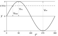
When a voltmeter measures AC voltage, it usually gives it in Vrms. Vrms = 0.707 x Vpeak.
What you see on your oscilloscope is Vpeak.
So to calculate gain, you need to make sure you are consistent in either using Vpeak or Vrms for both Vin and Vout.
To determine maximum power, input a signal and monitor the output voltage on your oscilloscope until you see the sine wave start to flatten or clip. That voltage is the clipping output voltage. The rms output power is calculated using the measured clipping voltage and the amplifier load resistance (the test load resistance).
P (Watts) = (Vrms x Vrms) / R where R = load resistance in Ohms and Vrms = Vclipping x 0.707
If you want gain in dB, gain in dB = 20 log (Vout/Vin)
When a voltmeter measures AC voltage, it usually gives it in Vrms. Vrms = 0.707 x Vpeak.
What you see on your oscilloscope is Vpeak.
So to calculate gain, you need to make sure you are consistent in either using Vpeak or Vrms for both Vin and Vout.
To determine maximum power, input a signal and monitor the output voltage on your oscilloscope until you see the sine wave start to flatten or clip. That voltage is the clipping output voltage. The rms output power is calculated using the measured clipping voltage and the amplifier load resistance (the test load resistance).
P (Watts) = (Vrms x Vrms) / R where R = load resistance in Ohms and Vrms = Vclipping x 0.707
Attachments
I mounted my thermistors flat on the big washers supplied with the chassis kit. I thought the bias drift was normal. Thanks for the info. This forum has been invaluable getting my F5T built. You guys rock!
Gain is the ratio of Vout/Vin. So you measure Vout and Vin and do the division.
If you want gain in dB, gain in dB = 20 log (Vout/Vin)
When a voltmeter measures AC voltage, it usually gives it in Vrms. Vrms = 0.707 x Vpeak.
What you see on your oscilloscope is Vpeak.
So to calculate gain, you need to make sure you are consistent in either using Vpeak or Vrms for both Vin and Vout.
To determine maximum power, input a signal and monitor the output voltage on your oscilloscope until you see the sine wave start to flatten or clip. That voltage is the clipping output voltage. The rms output power is calculated using the measured clipping voltage and the amplifier load resistance (the test load resistance).
P (Watts) = (Vrms x Vrms) / R where R = load resistance in Ohms and Vrms = Vclipping x 0.707
Thank you, I will check that out tonight.
luvrockin, just to follow up on Ben's post.
If you want to measure the max power, you will need to connect a load
(8 or 4 ohms are pretty standard). This is usually just a (very) high power
resistor. I use something like this:
8 Ohm 100W Non-Inductive Dummy Load Resistor
You can find others on amazon or that certain auction site as braking resistors.
For a higher power amp like the turbo you might want a 200W one.
Also, don't worry if you see your Vpeak (onset of clipping) on your scope being a few volts
below your rail voltage. This is expected.
Finally, depending on its design/spec, a multimeter might not measure a
1k sine wave accurately. (Some are meant for more standard AC voltage
frequencies) So that might be something to consider if things don't
match between your meter and scope after the RMS to peak voltage conversion.
Dennis, thank you and sounds good. How many volts does a normal preamp output to drive an amp at it’s max? My point is will I need to input more than 1 or 2 volts to get to max out prior to clipping? I don’t want to blow anything up with giving too high input signal.
The input signal level to start clipping is amplifier dependent.
Let's say your F5t has +/-34V rails under load and that there is adequate current
for the load in question so that clipping comes from voltage. Clipping will occur a
few volts below the rails, so let's say +/-30V. For a sine wave, this is roughly
21V RMS. An input signal of 1.75V RMS will produce this output, assuming a gain of x12.
This should give you a rough approximation. And when you amp is hooked up to the
scope and signal generator, just slowly increase the generator level while watching
for the onset of clipping on the scope.

nikwatt #853
Hello Nikwatt,
you always need good cooling in a F5T - my opinion.
What I saw - take care with the thermistor in direct contact with the aluminum heatsink! Those thermistors coating have failed in a few builds and made a short!
This is the reason why I glued my thermistors to the plastic body of the Mosfet.😉
Greets
Dirk 😀
Good morning.
I'm writing from Italy.
I'm bulding F5 turbo2
I'm using 4U HiFi2000 case. To increase dissipation I installed other front heatsink. Is it to much?
Furthermore 350mV is correct bias value?
Thank You
nicola
What Dirk said (easy to agree with someone that is always right and smarter than me).
«Correct» bias on the F5T depends on a number of factors. It is different from build to build. When you have solved the thermistor issue, I recommend you read the last 5-8 pages of this thread. Combination of too high bias and small errors/mistakes, can lead to blown parts. Watch your eyes.
Also, if you reread Nelsons article on this amp, he explains how the diodes can start to conduct (=imminent blow up risk) both from too high bias (400mv drop over source resistors), but also from too high temperature. The temperature vs conductance graphs should tell you what temps not to cross.
Temp is again dependant on dissipation vs heatsink. Dissipation depends on rail voltage and bias current (measured indirectly as voltage drop). So your «correct» bias could be lower or higher than 350mv. Probably lower. Correct in the sense that risk of blow-up is low.
Depending on your rail voltage, I would start far lower than 350mv drop. Maybe 280, and let it cook and see how the temps turn out.
But as mentioned, I recommend you read as much if this thread as possible, and Nelsons article on bias, and follow dirks advice. Much can go wrong.
Regards,
Andreas
Nikwatt - The small capacitors at C3 C4 must be stuffed with 1000pF, or you risk destructive oscillation.
to Andynor #855
Hello Andreas,
most often I feel like I know nothing.... 🙄
Learning every day - and made some experiences with my F5T....
Greets
Dirk 😀
Hello Andreas,
most often I feel like I know nothing.... 🙄
Learning every day - and made some experiences with my F5T....
Greets
Dirk 😀
I am in need of advise, I'm currently attempting to adjust bias and DC offset on my Mono block F5t v3. I have separate power supplies for each channel, my first attempt resulted in a very burnt Q3 where the Gate pin dissolved off the MOSFET.
I have 51vdc on the rails under no load, when I was adjusting bias the first time, the rail voltage was a very steady 48.1vdc with 200 mV of bias. My heat sinks are 10" wide X 14" tall with a 10mm base and 2" fins.
Each channel has two FE boards, 2 P channel boards, and 2 N channel boards. I have tested both mono blocks using the dim bulb tester and everything is good even with the output boards connected.
How do I measure DC offset? My first attempt, I had the DVM connected to each (+) & (-) output leads to the speaker terminals. No matter what adjustment I made, no noticeable difference was noted on the DVM for DC offset.
My other channel mono block is ready for adjustments and I am VERY unsure as to how to continue.
Should I measure DC offset for (+) to ground and adjust that FE boards P1 & P2?
Then do I measure (-) to ground and adjust the other FE board P1 & P2?
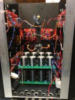
Here is a photo: Orange wires are OP, Red V+, Blue V-, Black is ground, Yellow is P channel gate and Purple is N channel gate.
I have 51vdc on the rails under no load, when I was adjusting bias the first time, the rail voltage was a very steady 48.1vdc with 200 mV of bias. My heat sinks are 10" wide X 14" tall with a 10mm base and 2" fins.
Each channel has two FE boards, 2 P channel boards, and 2 N channel boards. I have tested both mono blocks using the dim bulb tester and everything is good even with the output boards connected.
How do I measure DC offset? My first attempt, I had the DVM connected to each (+) & (-) output leads to the speaker terminals. No matter what adjustment I made, no noticeable difference was noted on the DVM for DC offset.
My other channel mono block is ready for adjustments and I am VERY unsure as to how to continue.
Should I measure DC offset for (+) to ground and adjust that FE boards P1 & P2?
Then do I measure (-) to ground and adjust the other FE board P1 & P2?
Here is a photo: Orange wires are OP, Red V+, Blue V-, Black is ground, Yellow is P channel gate and Purple is N channel gate.
Attachments
Last edited:
- Home
- Amplifiers
- Pass Labs
- F5Turbo Illustrated Build Guide