The FE board can be tested independent of the output boards.
The output boards can be tested independent of the FE boards.
For the FE board test, the JFETs are not needed while testing the cascode.
I usually populate the cascode first and test the voltage at their emitter, so that JFET D-S voltage is correct.
The JFETs come next, with a test across the 10 ohm resistor to check for JFET current, followed by a change in the output voltage based on trimmer position. Then set that back down to zero, checking that it has actually hit zero.
For the output boards, it is important to simulate a zero bias condition, achieved by shorting out the relevant pads. It appears to me that those pads are the gate (yellow and blue wire, far as I can tell, but don't hold me to it) and the power supply for the relevant board (red and black, in your case).
Once both are successfully tested, they can be connected together and it should work.
Disclaimer, I don't use separate boards - never have, never will, but I still use this process for testing. I also don't use the diodes as they are a possible point of failure - ambient temperatures here are significantly higher than the rest of the world and thermal performance is not predictable. Not had the misfortune of one failure till date, knock on wood.
Also, the F5T is not a complicated amplifier and there are only a very few failure mechanisms. Most of it is covered in the advice given to you by others (and by your self-discovery of user error) , maybe separately checking each board might cover all your bases.
Also, your troubles at first power-up and subsequent indicate that you might need new front end semis. That's new JFETs at the minimum. If the 2SJ74 broke down (which it might have done at 35V), the 2SK170 would definitely be toast. It wouldn't hurt to replace that set and give it a whirl, or pull them from the board and see if they are still working.
Dennis, I will check those resistor values tonight and the jfet positioning as well when I get off work. I’ll checked soldering and wiring too. I received my transistor tester yesterday, perhaps I’ll have an opportunity to use it.
I don't think we're at the boat anchor stage so don't despair yet. 🙂
You didn't measure the voltages across the 10 ohm source resistors R3 and R4.
I suspect they will be completely out of whack.
Can you check if the jfets (2sk170/2sj74) are in the correct spots? You will probably need to
cut off the zip tie you have on them and gently bend the jfets back.
Guys, thank everyone for the input and support. Dennis, you hit the nail on the head. I then checked the jfet and found the issue. My jfets were reversed on the boards. The J74 was installed on the + side of the board and the K170 on the - side. I removed them and they both tested good. I had another set which I purchased from the store just in case, so I installed them and I’ll save the removed ones. Unfortunately the new bipolars for Q7 & Q8 didn’t even ship yet, so this thing will come apart again next week but these cascode transistors seem to be working. I just don’t know if the are compromised being heated up that mush so I think I’ll just change them to be safe. I have to do the other channel in the AM. It’s now 1AM here. I was able to start setting bias and offset though. Thank you again.
The FE board can be tested independent of the output boards.
The output boards can be tested independent of the FE boards.
For the FE board test, the JFETs are not needed while testing the cascode.
I usually populate the cascode first and test the voltage at their emitter, so that JFET D-S voltage is correct.
The JFETs come next, with a test across the 10 ohm resistor to check for JFET current, followed by a change in the output voltage based on trimmer position. Then set that back down to zero, checking that it has actually hit zero.
For the output boards, it is important to simulate a zero bias condition, achieved by shorting out the relevant pads. It appears to me that those pads are the gate (yellow and blue wire, far as I can tell, but don't hold me to it) and the power supply for the relevant board (red and black, in your case).
Once both are successfully tested, they can be connected together and it should work.
Disclaimer, I don't use separate boards - never have, never will, but I still use this process for testing. I also don't use the diodes as they are a possible point of failure - ambient temperatures here are significantly higher than the rest of the world and thermal performance is not predictable. Not had the misfortune of one failure till date, knock on wood.
Also, the F5T is not a complicated amplifier and there are only a very few failure mechanisms. Most of it is covered in the advice given to you by others (and by your self-discovery of user error) , maybe separately checking each board might cover all your bases.
Also, your troubles at first power-up and subsequent indicate that you might need new front end semis. That's new JFETs at the minimum. If the 2SJ74 broke down (which it might have done at 35V), the 2SK170 would definitely be toast. It wouldn't hurt to replace that set and give it a whirl, or pull them from the board and see if they are still working.
Sangram, Thank you for this information. As a newbie, can you please explain the process of testing the individual boards a bit more? I listed a few questions below. I think that is an awesome idea and I was wondering if that could b done earlier but assumed no. Although I may be past that stage on this particular build, it’s definitely something I would like to do on the next.
“I usually populate the cascode first and test the voltage at their emitter, so that JFET D-S voltage is correct.”
How is this done and what should this voltage be or how would I arrive at knowing what this voltage should be?
“ The JFETs come next, with a test across the 10 ohm resistor to check for JFET current, followed by a change in the output voltage based on trimmer position. Then set that back down to zero, checking that it has actually hit zero.”
Are you confirming the bias pots work here?
“For the output boards, it is important to simulate a zero bias condition, achieved by shorting out the relevant pads. It appears to me that those pads are the gate (yellow and blue wire, far as I can tell, but don't hold me to it) and the power supply for the relevant board (red and black, in your case).
What is meant by “shorting out the relevant pads”? Do I not give this board power to test it? Do I short the gate to the power supply? I’m not following.
How is this done and what should this voltage be or how would I arrive at knowing what this voltage should be?
You would test the voltage between the JFET drain pad and ground (the JFETs are not populated at this time). The voltage should be close to the ratio of the cascode resistors.
Are you confirming the bias pots work here?
Yup. And that they're properly connected/oriented, and that you are able to get the correct biasing voltage on the output MOSFETs (about 5.5V is the maximum needed). This also helps to check the actual JFET current, which is handy to figure out whether they're in a safe operating zone.
What is meant by “shorting out the relevant pads”? Do I not give this board power to test it? Do I short the gate to the power supply? I’m not following.
1. Run a wire from the gate pad to the power supply pad for that board (for the P-ch board that would be positive supply for this amp).
2. Connect a 12V power supply between the PSU input (still with the P-ch board, this would be the +ve supply) and the output pad. Use a 10 ohm resistor in series with the power supply, not more than 1/2W. If everything is okay the resistor will survive, if not, you'll need to get back and check the board. When there is no bias (shorted G-S junction) the output board should draw zero current. If there's a problem, you only lose one small resistor.
Luvrockin, I'm happy you have located the problem. Since you already have
replacements ordered I agree with replacing the cascode transistors. If
nothing else, it'll save you from worrying about them in the future. 🙂
BTW, how did you test the jfets that were removed?
Cheers,
Dennis
replacements ordered I agree with replacing the cascode transistors. If
nothing else, it'll save you from worrying about them in the future. 🙂
BTW, how did you test the jfets that were removed?
Cheers,
Dennis
Thank you Sangram for this info. I may poke at you a little more later when this sinks in a bit. Dennis, believe it or not, the pair I pulled form the channel I did the most testing until discovery of the mistake test good, close to the new pair. Now the other channel jfets I only ran twice for a short period of time, never letting the cascades really heat up like the other channel, those jfets test bad? Go figure, either way they got replaced. Going to fire this channel up in a bit to start the procedure.
to luvrockin #808
Great that you found the issue!
Hopefully your F5T will come alive soon...😉
And don't be too fast at biasing up. Give it always some time to heat up and to
stabilize.
And. as higher the bias - as more sensitive are the pots to very small increments of a turn.
Greets
Dirk
Great that you found the issue!
Hopefully your F5T will come alive soon...😉
And don't be too fast at biasing up. Give it always some time to heat up and to
stabilize.
And. as higher the bias - as more sensitive are the pots to very small increments of a turn.
Greets
Dirk
(2) quick questions, when biasing how critical is it to have the jfets strapped together? I ran out of zip ties and will need to run out. I just need to know if I should go now or a bit later.
Also, someone mentioned glueing down thermistor on the output transistor. What type of glue should I use to glue them down on the MOSFET?
Also, someone mentioned glueing down thermistor on the output transistor. What type of glue should I use to glue them down on the MOSFET?
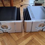
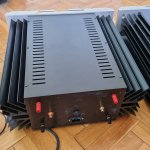
Here are the two amps. Very pleased with the sound, big thanks to both Nelson Pass and also to diyaudio 🙂
The PSU boards are own design as the ones from the store got stuck with US mail (arrived in Jan 2021, however). I didn`t add the optional stability caps recommended by 6L6 but at least at 1Khz the square wave response was almost perfect with very very tiny overshoot (was so low I decided not to add the caps).
Yesterday at 25C ambient the amp got to 53C so I saved some money from my gas bill 🙂)
Attachments

Last edited:


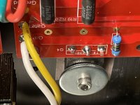
Hello guys, I was getting my F5T running yesterday. I let it cook most of the day setting bias and observing its operation. After the biasing was complete, I put an 8 ohm dummy load on it and let it set. Everything still seemed ok. The resistor remained cool to the touch. I was going to put a test signal through it to see what it looks like on a scope when out of the corner of my eye, I saw a spark fly under the cover. I immediately shut it down and was trying to see where it came from. I didn’t see anything right off so I turned it back on. I saw some smoke starting to come from the from the Q4 output MOSFET in the P channel. I eventually found where the spark flew from. I used the small washers under the screws in the corners of the boards and it just barely caught the trace and cut through. I pulled the boards and checked. The Q4 MOSFET on the p board is shorted throughout. Mouser numbers are 844-IBRF9240PBF & 844-IBRF920PBF made by Vishay in stock. I know these are supposed to be matched pairs on the channels but can these be used? The other option is to buy another whole kit from the DIY store which is $90 which I’d like to avoid if possible.
IRFP9240PBF Vishay Semiconductors | Mouser
IRFP240PBF Vishay Semiconductors | Mouser
I wanted to add a quick question too. I noticed when my amp is cold, is it normal for the bias to be much higher than where it was set at hot? Yesterday I finalized biasing for now at about 330mv but after the issue inside, I disconnected the problem side and turned on the amp again to watch the good channel and noticed my starting bias was up in the low 400’s. I shut it down after a bit and thought I would ask you guy’s opinions.
Attachments

Last edited:
Aw man! 🙁
You deserve a merit badge for sticktoittiveness.
Someone should correct me if I am wrong. I believe the Ps match Ps and the Ns match the Ns. Difference accounted for via offset adjustment. So, if I'm correct, you'll replace the Ps, not all the Ns and Ps.
I'm not sure where you are, but I can send you a matched set of Ps, no charge. Note: They are Vishay. Other manufacturers may be preferred, and I'm not sure what the store uses or if mixing manufacturers is advised.
I'm confident enough in my matching to think it will not cause you problems. I've used them in all but one of my DIY amps. No little current hogs found. Given how often these are used, perhaps someone closer to you has a set and can get them to you faster. Either way, the offer stands. Reach out via PM if you'd like a few.
Best,
Patrick
Last edited:
- Home
- Amplifiers
- Pass Labs
- F5Turbo Illustrated Build Guide