
#2,618
"Measure twice, cut once" translated into electronics. "Choose an acceptable LED brightness (get your spouse's approval too) before calculating its current limiting resistor value".
Futz around on the test bench with milliammeter, variable DC supply, 10K resistor, and LED. Dial up and down until "perfection" is reached, get approval, write down LED current in your lab notebook, done.
The key part is to write down the resistance for future use with that particular LED. If you bought a quantity, add a note to the storage container/bag with your determined resistance.
But the resistance is voltage dependent, so the resistance will only apply for that particular voltage.
Relating current to a LED brightness is more appropriate. Then the resistance can be calculated for any voltage.
Relating current to a LED brightness is more appropriate. Then the resistance can be calculated for any voltage.
The key is to write down the CURRENT for future use with this particular LED.
LED_series_resistance = [ (Supply voltage) - (LED forward voltage) ] / CURRENT
Resistance must change when supply voltage changes, and since Murphy's Law says your next project will operate at a different supply voltage than your current project: therefore to operate the LED at the same CURRENT {same brightness}, new project with new supply voltage requires new resistance value.
My mistake: I was thinking of Pass amp projects which seem to use same PS voltage. I am chastened! But the basic idea of keeping the info in the storage container seems to be a good one…
Let me work out the range of resistance needed for supply voltages from 5 to 250 volts, and the lowest and highest currents for LEDs based on a scan of on Mouser and Digikey. That may help set a better value for the resistor and hopefully ensure that trim pot value is sufficient to proved the full range.
For the LED,
ZM's Thumb of Rule - 1K per each Volt of PSU
if too bright (not likely) just add 50%
My standard method:
Hook an ordinary potmeter, lets say 150-200 k inline with one of the led leads. Turn it to full resistance. Connect the potmeter and the other lead from the led to the psu or whatever. Turn it on. Slowly turn the potmeter towards zero ohm. Stop when the led light "is about right". Disconnect the potmeter, do NOT turn the pot. Measure the resistance in the pot, pull out your resistor selection and find one which is about the same. Solder one end to one of the led leads and and the other to some length of wire. Cover with some heatshrinking tube. Solder a similar length of wire to the other lead wire and cover with some heatshrinking tube. Observe the direction of the led and connect the wires to the psu or whatever. Done.
Hook an ordinary potmeter, lets say 150-200 k inline with one of the led leads. Turn it to full resistance. Connect the potmeter and the other lead from the led to the psu or whatever. Turn it on. Slowly turn the potmeter towards zero ohm. Stop when the led light "is about right". Disconnect the potmeter, do NOT turn the pot. Measure the resistance in the pot, pull out your resistor selection and find one which is about the same. Solder one end to one of the led leads and and the other to some length of wire. Cover with some heatshrinking tube. Solder a similar length of wire to the other lead wire and cover with some heatshrinking tube. Observe the direction of the led and connect the wires to the psu or whatever. Done.
I plan on connecting a voltage regulator to the +24V rail and GND to power a microntroller and use PWM output to dim the LED. ( maybe with a zener before the voltage regulator ) I"m curious to find out if anyone has tried this before and if so, did it result in any problematic noise that would affect the sound quality at all? I think someone mentioned if I was worried about noise to leave it out of my design, but I'm more curious about finding out if anyone has experience trying this out and what they observed as far as noise. I could start a new post, but I'm still working on the F5m and want to look into how it will affect this particular circuit.
That's a lot of work when one resistor will do the job. 🤓
One resistor will glow the LED for a few minutes to indicate the amp is warming up, or be just as bright in the daytime as the night time and change colors or flash for other stuff? So much resistance to this idea.
Good one! I see it's a bad idea, we can move on now. ( pollute the thread )
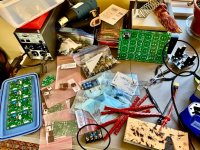
Here’s a bit of said pollution:
Note: Building 3 F5m’s for the boy’s and girl’s who have been naughty but nice in my life this past year plus a pair of mono’s for self. Apologize for the off topic blurb!
Chuckle’s …. Sorry have somehow managed to lose your email address but remember you mentioned following this thread?
Anyways… Thank’s for all the extra effort … I’ve managed to scrounge up the missing part(s). Just wasn’t digging deep enough into my old parts hoard and ended up only ordering one missing resistor to finish the pile-o-board’s.
In answer to questions about the mess of F5m parts.
The inrush thermal terminal block(s) is silver soldered but it’s for a different valve/tube build. The assembled pcb blue board is one of a pair of a pair of 24 V “Silent Switchers” I’m putting together. Thank’s for the offer and time.
Best
Attachments
I like to power LEDs with a CCS. Just adds a cheap J109 or whatever for Rlim + trimpot in Vgs. Some FETs might not need Rlim.
Hello,
I've had the F5m up and running for about 2 weeks now. Very nice, really enjoying the old music and the new music. I have built some audio equipment but only one other power amp, this build was a definite step up for me. This thread was very helpful in not only guiding the build but understanding the build. The conversation is very much appreciated by this lurker. Looking forward to putting together an Aleph!
Cheers!
Here’s a bit of said pollution:
Note: Building 3 F5m’s for the boy’s and girl’s who have been naughty but nice in my life this past year plus a pair of mono’s for self. Apologize for the off topic blurb!
Chuckle’s …. Sorry have somehow managed to lose your email address but remember you mentioned following this thread?
Anyways… Thank’s for all the extra effort … I’ve managed to scrounge up the missing part(s). Just wasn’t digging deep enough into my old parts hoard and ended up only ordering one missing resistor to finish the pile-o-board’s.
In answer to questions about the mess of F5m parts.
The inrush thermal terminal block(s) is silver soldered but it’s for a different valve/tube build. The assembled pcb blue board is one of a pair of a pair of 24 V “Silent Switchers” I’m putting together. Thank’s for the offer and time.
Best
 Are those twizzlers on the bench… or god forbid…. Red vines? Everyone knows that twizzlers produce at least 2 ppm better THD.
- Home
- Amplifiers
- Pass Labs
- F5m kit