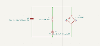
Something like this?
...oh.. I think I made a mistake... will update schematic soon.
...oh.. I think I made a mistake... will update schematic soon.
Attachments

Last edited:
Also, is it ok to add an STM32 microcontroller inside the case or should I worry about high frequency interference? What if I include a USB port, or wifi? I'm wondering if this should be a concern for the audio quality. ( example, running PWM to dim led )
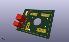


Just thought a pcb could be stacked on top if there is little room on the floor, but then again the holes do take up more room.
Also note I didn't use standard spacing for holes so standoffs will not match up with the bottom grid holes. I could remove the holes if I do another version to save the space.
Also note I didn't use standard spacing for holes so standoffs will not match up with the bottom grid holes. I could remove the holes if I do another version to save the space.
Last edited:
Yes standoffs are unnecessary.
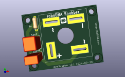
Also, you don't need to have the positive and negative be solderable. It takes a lot of heat to solder the bridge terminals so if you make them unsolderable then people won't waste the extra effort. You can replace that pad with just a slot hole.
Third note, make the hole for the screw as large as you can so that way screw heads can fit through and mount directly to the rectifier instead of to the board.
Voila, the perfect rectifier snubber board. I drew some up a while back but haven't had them printed yet because I've been too lazy. LOL
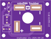
Thanks, the hole should be large enough for the head of the screw to pass through the board.
I started a new thread 'Rectifier Snubber - roboDNA' to avoid polluting this one.
I started a new thread 'Rectifier Snubber - roboDNA' to avoid polluting this one.
Hi, I'm a newbie and have a silly question.
I'm making a mono block f5m now. But, I don't know how to connect PSU ground properly. Is it safe to connect PSU ground with one ground point on chassis, which is already connected with toroidal shield and ground from 110v AC socket.
Thanks in advance.
Hayoung
I'm making a mono block f5m now. But, I don't know how to connect PSU ground properly. Is it safe to connect PSU ground with one ground point on chassis, which is already connected with toroidal shield and ground from 110v AC socket.
Thanks in advance.
Hayoung
^ Which ground are you specifically referring to as "PSU Ground"? Please post a picture of the board and circle the spot, and/or post a reference to the schematic.
Why? Because PSU ground may mean "mains earth/safety ground" or the 0V "audio GND" for the circuit. We just need to be sure.
Separately, you'll see lots of advice around having one single very reliable attachment from mains earth / safety ground to the chassis with no other connections sharing the same point of contact at the chassis. However, you'll also see many wonderful examples of builds in the forums that do not follow that practice.
Personally, I like this explanation quoted below from the page linked below. YMMV.
"The mains safety earth must be connected to a separate bolt, whose sole purpose is to provide a solid earth connection to the equipment chassis. Where there are separate removable panels, it may also be a requirement where you live that these have a wired connection to the main chassis. This prevents any possibility of the removable panel from becoming 'live' should an electrical fault cause the mains to be in contact with the panel - regardless of whether the securing screws are installed or not."
https://sound-au.com/psu-wiring.htm
This is a good question and I'm now thinking about how to handle grounding the whole chassis.
If the top, bottom and rear panels are powder coated, do they still need to be earth grounded like the rest of the chassis? I know when I buy equipment from amazon, I test the case/tool to see if it's grounded. Should the screws be used to ground 2 panels together, or it it better to run a grounding wire between the 2? I recall sanding down around the panel screw hole to ensure the screw conducted to the other panel when attached. ( this was for a desktop solder fan which had a powder coated case, but designed to also have screws which connected case to earth grounded chassis. the solution was to sand down the powder coat around the screw hole )
If the top, bottom and rear panels are powder coated, do they still need to be earth grounded like the rest of the chassis? I know when I buy equipment from amazon, I test the case/tool to see if it's grounded. Should the screws be used to ground 2 panels together, or it it better to run a grounding wire between the 2? I recall sanding down around the panel screw hole to ensure the screw conducted to the other panel when attached. ( this was for a desktop solder fan which had a powder coated case, but designed to also have screws which connected case to earth grounded chassis. the solution was to sand down the powder coat around the screw hole )
Yes definitely verify that all panels / heatsinks are earth grounded. Removing the powder coat at the attachment points is certainly a good idea. On the preamp in my signature, I added ground wires between the aluminum side panel heat spreaders and the steel mounting plate on the floor, for better sleep at night...
On the same topic, I plan on using a spade connector for wires between the transformer and the rectifier tabs. Is there a way to ensure those spade connectors stay in for the long run? I know I've used spade connectors for speakers before and they have become disconnected at times. It seems like a weak point to me but not sure since it's my first amp build. Maybe I can use the holes on my snubber to have 3d printed brackets to lock or zip-tie the spade connectors on @birdbox Or maybe I should have kept the screw header on the snubber board 😉
Update: The spade connectors do seem to be on there fairly good though, even after attaching/removing them a couple dozen times. I guess it's all good. ( I'll just add a bit of shrink tubing at the spade connector end to make sure it's all covered )
Update: The spade connectors do seem to be on there fairly good though, even after attaching/removing them a couple dozen times. I guess it's all good. ( I'll just add a bit of shrink tubing at the spade connector end to make sure it's all covered )
Last edited:
There is a hole on on spade connectors. The female connector connected to the wire should have a little bump that is made to Engauge with the spade. Or you could simply solder the wires in... 🤔Is there a way to ensure those spade connectors stay in for the long run?
BTW, leaving the spade connector exposed will allow you to put a pick in the spade to depress the little bump that engauges with the hole. That way you can remove the spade easily. Also a place to put a multimeter lead.
Thanks for your link. It answer my question.
Maybe I missed this, but for which IDSS do the SK170/SJ74 in the F5m kit have to be matched?
BR Barossi
BR Barossi
I'm wondering if it would make sense to replace the JFET's from the F5m kit. How well are these selected?
There are alternatives in the DIYAUDIOSTORE:
https://diyaudiostore.com/products/matched-jfets?variant=39335246889033
Toshiba?
LSK?
There are alternatives in the DIYAUDIOSTORE:
https://diyaudiostore.com/products/matched-jfets?variant=39335246889033
Toshiba?
LSK?
Is there any update on a build guide? Should I plow ahead under the watchful eye of my electrical engineer brother-in-law or Wait for the guide...or both!? Thanks!
- Home
- Amplifiers
- Pass Labs
- F5m kit