
During the BAF talk, someone mentioned troubleshooting an issue where the transformer was making contact with the case somehow and earth ground prevented a shock when touching the case. How would this type of short have been detected using a DM? I would like to add several 'test points' in my build guide to allow checking of these types of shorts before powering up. For example, I'll be adding a 'test point' to ensure the rectifiers are not shorted by the snubber board. I would also like to add details in my case build guide to identify where toothed washers should be used, and where case panels need to be attached to ensure earth ground throughout. If anyone suggests test points, I can ensure they are in the guide(s).
I would think that with amplifier unplugged, you should have an open connection between chassis ground and line. Also chassis ground and neutral. Also, on the secondary side, check each secondary against ground.
I have a little check list that I do. I check:
V+/gnd
V-/gnd
line/gnd
neut/gnd
secondaries to gnd
V+ and V- attached in the correct positions on the PS board
The V+ and V- to gnd has saved me in regards to a bad insulator on a mosfet in the past...
I have a little check list that I do. I check:
V+/gnd
V-/gnd
line/gnd
neut/gnd
secondaries to gnd
V+ and V- attached in the correct positions on the PS board
The V+ and V- to gnd has saved me in regards to a bad insulator on a mosfet in the past...
I'm looking for a good way to connect the 2 line and 2 neutral wires from the transformer to the screw header on the small 'Randy A/C splitter' board. I tried inserting 2 red wires from the antek transformer into the grey 16awg end terminal connector and could not fit them, and also noticed the connector does not fit into the screw header. I could tin the 2 wires together and just insert those into the screw header but should I use the terminal connector? ( I see pictures from another build appears to use the grey 16awg connector with 2 wires inserted into it, and then into the screw header )
I've had good success purchasing a (ferrule kit) and then inserting the two wires into the female side of an appropriate ferrule. Crimp with the death grip of a thousand demons from hell, and presto: it's strong, tidy, and electrically excellent.
I liked my ferrule kit so well that I commanded Amazon.com to send another one of those kits to moderator @6L6 and he loves them too.
I liked my ferrule kit so well that I commanded Amazon.com to send another one of those kits to moderator @6L6 and he loves them too.
It was this thread: https://www.diyaudio.com/community/threads/need-help-with-f5m-build.418462/During the BAF talk, someone mentioned troubleshooting an issue where the transformer was making contact with the case somehow and earth ground prevented a shock when touching the case. How would this type of short have been detected using a DM? I would like to add several 'test points' in my build guide to allow checking of these types of shorts before powering up. For example, I'll be adding a 'test point' to ensure the rectifiers are not shorted by the snubber board. I would also like to add details in my case build guide to identify where toothed washers should be used, and where case panels need to be attached to ensure earth ground throughout. If anyone suggests test points, I can ensure they are in the guide(s).
He used the DVM to check all transformer leads against ground: https://www.diyaudio.com/community/threads/need-help-with-f5m-build.418462/post-7813953
I did purchase one of those kits at your recommendation I think... I now realize once I apply demon level pressure using the ratchet tool, the the grey 'ferrule' tip will then fit into the screw header. The 'ferrule' is too large before the crimping so I was stumped. I'll need to use some force to get those 2 wires to fit into the female end of the 'ferrule' though.I've had good success purchasing a (ferrule kit) and then inserting the two wires into the female side of an appropriate ferrule. Crimp with the death grip of a thousand demons from hell, and presto: it's strong, tidy, and electrically excellent.
I liked my ferrule kit so well that I commanded Amazon.com to send another one of those kits to moderator @6L6 and he loves them too.
UPDATE: I was able to fit the 2 wires into the ferrule however after crimping, it still does not fit in the screw header 🙁 I'll try a smaller ferrule but the wire insulation will not fit into the collar of the ferrule for 2 wires. Funny that I see another build using the grey ferrule and it fits. Perhaps they used a screw header with larger holes.
Last edited:
Perhaps insulation should not be inserted into the ferrule collar? Only the stripped conductor wire? I’m not sure if the collar provides strain relief. I’ve also cut off the insulation of the collar of Fastons, and then used a screwdriver to enlarged the diameter of the collar to allow wires to fit in before soldering or crimping. Then apply colored heat shrink,
You are correct, I did get the 2 wires into 1 grey 16awg ferrule. For some reason, the tip of the connector does not fit into any of the screw headers I have, and the ones I see on mouser all seem to have the same size hole. They all seem to have a range of 12-24awg. If I need to force it into the screw connector, I may try to find a different way.
Maybe I can splice the 2 wires together before the ferrule, add some shrink tubing, and then only have 1 wire going into the blue/smaller ferrule and then into the screw header.
I'm also considering just soldering wires directly to the splitter board, ( removing the screw headers ) and using 4 pin molex connectors like a PC power supply. ( I checked and PC power supplies have the molex connector wires soldered directly to the board )
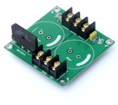
My preferred choice so far is the screw terminal like the ones I show in this picture but I may need to spin up a new board. I'll check to see if the footprint will work.
Maybe I can splice the 2 wires together before the ferrule, add some shrink tubing, and then only have 1 wire going into the blue/smaller ferrule and then into the screw header.
I'm also considering just soldering wires directly to the splitter board, ( removing the screw headers ) and using 4 pin molex connectors like a PC power supply. ( I checked and PC power supplies have the molex connector wires soldered directly to the board )
My preferred choice so far is the screw terminal like the ones I show in this picture but I may need to spin up a new board. I'll check to see if the footprint will work.
Attachments
Last edited:
Well, problem solved. I looked at the PCB and sure enough, I don't need to stuff 2 wires into 1 connector. I went on a bit of a goose chase after seeing the following image and seeing 2 red wires stuffed into 1 grey connector, and same with the 2 black wires. One of the the board's input show N/C so I figured not connected. I just 'assumed' I had to do the same for some reason, but now see the randy splitter board allows each wire to be connected into their own screw hole. my bad. I can now proceed.
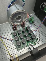
Update: I used the black 16awg ferrules on the end of each of the 4 wires and they fit perfectly into the screw headers. Seems solid to me. I wonder if the screw in the screw header header loosens up over time... Maybe I can add blue loctite or use the larger black barrier terminals with new boards.
Update: I used the black 16awg ferrules on the end of each of the 4 wires and they fit perfectly into the screw headers. Seems solid to me. I wonder if the screw in the screw header header loosens up over time... Maybe I can add blue loctite or use the larger black barrier terminals with new boards.
Attachments
Last edited:
Ok, that makes sense. I can see how using solid core with terminal blocks is ok, but the bootlace ferrule is needed for stranded. ( prevent wiskering )
Maybe in the future I'll revisit and use something like the vertical pcb mounted molex receptacles like these ( include 2 red and 2 black in 1 molex ). I would use two 4 pin connectors.

Maybe in the future I'll revisit and use something like the vertical pcb mounted molex receptacles like these ( include 2 red and 2 black in 1 molex ). I would use two 4 pin connectors.
^ There have been extensive discussions re: wire attachments / connections / terminations throughout the forum.
What I try to do is:
- If I'm using a crimped terminal, ensure that the termination is designed for the wire (type, gauge, and insulation) I intend to use (or vice versa). Once that termination is chosen, use a properly designed and set-up crimping tool. The tools (or dies) are usually specific to the type and/or size of termination. "Crimping", I think gets a bad rap b/c of poorly executed crimps. Poorly executed crimps are usually user error.
- Soldering is also wonderful. I use it quite a bit when I know the connection isn't likely to be changed by some nutjob that likes to move things around all the time (me). Soldering is a lot faster, for me, than creating a proper crimped termination, but I don't like de-soldering. So, for things I know I'll likely move or change, I typically have one end of each wire soldered, and one end with some sort of "easy release" termination. It also makes assembly, disassembly, and service easier for me.
Separate, but related to above, those terminations in your photo can be fiddly to crimp properly, IMO. If you buy a bunch of them and practice with the tool specifically designed for them, I think you'll be pleased with the outcome.
Once again... YMMV. I love that you're exploring options that work best for you, and that you're thinking about how it could be easier for others. You'll get lots of excellent opinions.
Have fun!
I think the bootlace ferrule and screw header is the best so far. I guess another option could be to solder the wires directly to the board and add a small hole in the board or plastic standoff with loop to zip tie the wires. Or could extend the PCB just for a ziptie hole.

Doesn't Molex requires a special crimping and insertion tool, and extraction tool? Cost of these application-specific tools (esp criming tool) can be very pricey, I've noticed, based upon researching other connectors.Ok, that makes sense. I can see how using solid core with terminal blocks is ok, but the bootlace ferrule is needed for stranded. ( prevent wiskering )
Maybe in the future I'll revisit and use something like the vertical pcb mounted molex receptacles like these ( include 2 red and 2 black in 1 molex ). I would use two 4 pin connectors.
@ItsAllInMyHead we're on the same page, my answer was simply incomplete. I use boot-lace ferrules with stranded wire when the terminal uses a bare set-screw like euro strips. My preference is to use terminals with a pressure-plate and avoid the crimped ferrule altogether. Bare screw terminals that require a wrap around the screw shank are another matter with some being listed for stranded wire (power outlets and switches commonly) but I avoid those as well and only buy commercial switches/outlets that utilize a pressure plate.
As previously noted, UL listed crimp connectors are intended to be used with the specific crimper used to obtain the approval/listing. While the NEC doesn't address the internal wiring of amplifiers or other gear in question here, it's general suitability remains. The UL White Book is another useful resource along with the ABYC Standards for marine wiring.
As previously noted, UL listed crimp connectors are intended to be used with the specific crimper used to obtain the approval/listing. While the NEC doesn't address the internal wiring of amplifiers or other gear in question here, it's general suitability remains. The UL White Book is another useful resource along with the ABYC Standards for marine wiring.
@Halauhula True, the cost can be a problem with not much value added.
@seventhenths, do you have a mouser part as an example of a pressure-bar type connector with a small enough footprint, in stock, and not too expensive? I recall looking into the grey/orange ones but did not see any PCB mounted ones, and all the ones I saw were quite large. Pressue bar does sound very good...
@seventhenths, do you have a mouser part as an example of a pressure-bar type connector with a small enough footprint, in stock, and not too expensive? I recall looking into the grey/orange ones but did not see any PCB mounted ones, and all the ones I saw were quite large. Pressue bar does sound very good...
- Home
- Amplifiers
- Pass Labs
- F5m kit