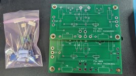
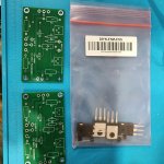
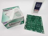
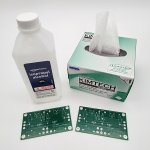
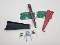
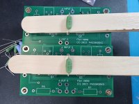
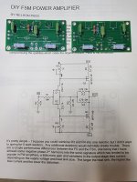
Certainly getting the boards populated should be pretty straight forward. You can use the Alpha Jzm guide to understand a little bit about the wiring. A lot of the basic stuff you want to do is in other guides such as...(clean the boards first with isopropyl alcohol, print out schematics and layouts from article to check off parts as you populate, measure your resistors before installing, lift the larger resistors off the board ~0.25" to ensure maximum cooling, start with smallest components first (except if you are going to use tongue depressors for lefting the large resistors up off the board, then do large resistors first), be gentle with JFETs, (leave long leads and be sure to get orientation right), clean boards after done, do quality assurance checks on the joints, and take lots of pictures!). Don't install the large MOSFETs until after the boards are mounted onto the heat sinks and the proper Keratherm pads (or other isolation) are installed.
I know a couple of folks are working on build guides right now specifically for the F5m, but the overall theme is the same if you look at other build guides and I believe the details that are different are found in Nelsons's F5m article.
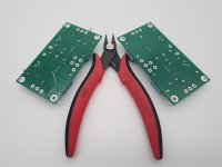
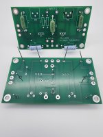
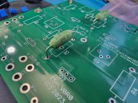
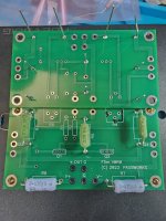
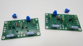
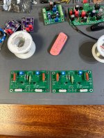
One should at the very least be able to populate the boards themselves as there is a very low part count and Nelson's article can be followed to check off items as you install. I think the PSU board can be populated pretty easily as well. That leaves you with all the wiring, which I find to be the most time consuming part.
I know a couple of folks are working on build guides right now specifically for the F5m, but the overall theme is the same if you look at other build guides and I believe the details that are different are found in Nelsons's F5m article.
One should at the very least be able to populate the boards themselves as there is a very low part count and Nelson's article can be followed to check off items as you install. I think the PSU board can be populated pretty easily as well. That leaves you with all the wiring, which I find to be the most time consuming part.
Attachments
-
 20240910_185001.jpg396.5 KB · Views: 228
 -
 20240909_172729.jpg488.8 KB · Views: 173
 -
 20240926_202541.jpg336.5 KB · Views: 168
 -
 20240909_204022.jpg359.5 KB · Views: 173
 -
 20240910_190047.jpg229.2 KB · Views: 182
 -
 20240910_193404.jpg303.9 KB · Views: 179
 -
 20240910_190334.jpg480 KB · Views: 177
 -
 20240910_192820.jpg240.5 KB · Views: 167
 -
 20240910_192524.jpg354.9 KB · Views: 178
 -
 20240910_191427.jpg436.6 KB · Views: 177
 -
 20240910_192241.jpg520.2 KB · Views: 189
 -
 20240918_235215.jpg197.6 KB · Views: 215
 -
 20240918_234359.jpg237.2 KB · Views: 259
 -
 20240910_200256.jpg435.5 KB · Views: 260
Last edited:

Thanks that's all a huge help I'm pretty solid on almost everything after messing around with the ACAs following tungsten's mods etc.. the new part for me will be the AC wiring., but I'm going to start fitting everything together, and it's nice to know there's always help here with questions!
This was a question for me too. Post #808 tells you what safety cap to use (X1Y1 rated 3300pF ) and post #809 has some clear pictures that I used as a guide for AC wiring and everything worked out fine! Thanks 6L6!the new part for me will be the AC wiring


^ Doesn't look to be an issue on your end @Monk55
Some may have noticed that uploaded pictures do not display.
The forum software has just been upgraded, and this problem has yet to be resolved.
I didn't test, but external hosted images will most likely work.
Hugo
The forum software has just been upgraded, and this problem has yet to be resolved.
I didn't test, but external hosted images will most likely work.
Hugo
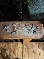
Were these part of a kit from the store?When you try to find the melting point of your SL22’s….by accident!! I missed them in the box I used to start a fire…..


See #2145
Aha… those photos didn’t upload because of the forum migration. Can you ( @Monk55 ) see them?
No…just the last oneAha… those photos didn’t upload because of the forum migration. Can you ( @Monk55 ) see them?
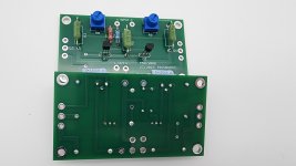
I suspect I'm probably the only one who got confused with how to implement the F5m Pass Bipolar PSU's for dual mono, but I'll post this anyway. After spending a couple days perplexed on how to "jumper" the PSU's properly I finally figured it out with a little inspiration from @ItsAllInMyHead .
I guess I had to expand my mind to understand that jumpers can be more than 1/2" long, and once I wrapped my mind around that, it all came together. Just goes to show that one's internal "bias" can really blind oneself. Now that I see how to do it, I feel like a total moron that I was so perplexed, but just in case it helps someone else avoid some head scratching I'll post how to do it below now that I've figured it out.


I guess I had to expand my mind to understand that jumpers can be more than 1/2" long, and once I wrapped my mind around that, it all came together. Just goes to show that one's internal "bias" can really blind oneself. Now that I see how to do it, I feel like a total moron that I was so perplexed, but just in case it helps someone else avoid some head scratching I'll post how to do it below now that I've figured it out.
Last edited:
- Home
- Amplifiers
- Pass Labs
- F5m kit