Ok great, that makes sense. I do have some of those green terminal blocks. If soldering directly to the PCB is what FW did, than that is good enough for me. Just for reference, my initial concern was about having wires directly soldered to the board. I'm envisioning the cable's contact point to the pad with most of the tension placed on a smaller soldered surface area around the wire strands than there would be with an end post. I'm thinking if the wires wiggles around back and forth or move over a longer period of time, strands in the wire may start to break, specially if someone is working on it. Could a post spread/disperse the tension over a larger surface area to prevent this type of wire failure? The tension would be spread over the metal post/rubber collar and not wires strands directly. I know over the years I have seen boards where wires were partially broken at the board when soldered directly. Again I'm not trying to say one is better, just learning how to make it a first-class build.
I have an electric de-soldering pump so removing wires directly soldered to the board is a trivial task for me.
I have an electric de-soldering pump so removing wires directly soldered to the board is a trivial task for me.
What is going to make the wire wiggle to the point of failure? Your stated example sounds like an error of some kind during assembly or repair...
Anyway, make gentle curves in the wiring and you'll have more than enough give for any thermal changes.
Anyway, make gentle curves in the wiring and you'll have more than enough give for any thermal changes.
Transporting the amp, and other vibrations maybe, I don't know. I do know for certain I have seen wires failed at the board many times, but could not give you the manuracturer. May have been my own motor control boards. I'm sure others have seen this type of wire failure. Since the wire is not compacted at the PCB when soldered, it could be up to individual strands to take the tension and in turn fail over time. Again, not looking to convince anyone of anything, I'm just gathering info. for myself to understand the design considerations which have gone into the build. I realize posting a question may seem like I'm trying to dispense wisdom but it's the opposite. I'll just move on from this topic since FW soldered directly to the board and apparently this has not been an issue ever. ( not related to F5m build )
Even with my non-pro soldering, there is no way any wiggling will affect these joints. I recently took my F5m boards off of sinks to use another project. Wires inserted in the PCB holes and soldered with non-fancy Kester. I don’t understand the concern.
Attachments

@roboDNA - Related to above... if you're worried about strain, the input wiring is where you may want to be a tad careful, but ... as long as you don't use something like 30AWG solid / single strand... it'll all be easy peasy. Don't sweat it.
Also... you may find that if you tin the wire before you solder it to the boards, your life will be a little easier.
Also... you may find that if you tin the wire before you solder it to the boards, your life will be a little easier.
True, tinning will help big time. Also, I noticed on some nicer boards the wire has insulation pulled up snug to the board which acts as a collar. No concerns at all other ensuring this is the best way to go. Thanks for all the input, I've locked in the solution so good to go now.
I suspect that the tube preamp may use an older grounding scheme that is leading to hum when it is in the signal chain. It has been common practice for tube gear to use the steel chassis as a distributed ground. This tends to be true even with tube gear of recent manufacture. Carefully removing the bottom plate of the chassis will reveal how the grounds are connected.
Another quick test is to reverse the polarity of the AC power plug where it is connected to the wall. This can make a difference due to the way the high voltage power transformer primary winding are connected to tge AC inlet.
Remediation of grounding schemes with tube gear can be quite complex. Perhaps more than can be easily covered in this thread.
PL and First watt have soldered connections. PL having some ribbon cabling I suspect due to the number of connections needed and UGS on connectors for in-the-field serviceability. First watt amps, which are more comparable to what we are dealing with, are all soldered...If soldering directly to the PCB is what FW did, than that is good enough for me.
I haven't heard Pass's wire connections failing. I have seen old PCBs where the traces are all on one side have issues with the pad pulling off. However, these newer boards are 2-layer which means each pad is pretty much a large via. So they are really tough.
Use good solder. I use Cardas and DIYaudio's fireball because they are especially easy to work with. Kester also works great.
Let the solder wick into the wire. Then give it a touch more rosin core solder to give it a bit more flux so it reflows a bit more. that will provide a great connection. You can also work your soldering iron around the wire as you solder it to spread the heat around. Assuming the clearances are not to close on the wires, I tend to strip the wire a bit further than needed for the connection lifting the exposed threads above the board. This allows me to solder the wire from the top. This also allows me to clamp a meter to the bare wire for testing and desolder the wire without taking the boards off.
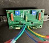
In the spirit of this soldering talk, I just did an experiment. I pulled out a board that I had printed from JLCPCB. Just your standard run of the mill board. The wire is silicone insulated 16awg stuff from amazon and the solder is cardas. You can see how I like to solder them in the picture.

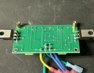
I tied one of the secondaries of a 400va 18vac tranformer from Antek and let the transformer hang from the wire connection. Swung it around for a minute. and then checked it. I was only slightly carefull as I was more worried abou the secondary wire. Although I did zip tie the secondaries together for the test...

Here is the after...

I tied one of the secondaries of a 400va 18vac tranformer from Antek and let the transformer hang from the wire connection. Swung it around for a minute. and then checked it. I was only slightly carefull as I was more worried abou the secondary wire. Although I did zip tie the secondaries together for the test...
Here is the after...
Maybe it is just me, but I never had a lot of luck with tube preamps and First Watt Clone power amps. I used to be an all tube guy,
no sand amps period. Then I built the original F5 and that changed everything. My preamps were tube, so one of them was hooked up to the F5.
Sound was OK, but bias tended to jump around a bit more than usual, things just not as stable. This was never a problem feeding a tube amp.
I see people here using tube preamps, phono tube preamps etc with these clones, I guess for more tube warmth or something. I just was never comfortable with tube pre and phono pre amps in front of a solid state amps. If I want tube warmth, I would use a tube power amp! This led me to building Pass clone preamps, now I havent built tubes for years. With the solid state Pre, like BA3 pre, 2018 line stage, B1, Iron pre etc, everything is stable as can be, sounds great and I am happy.
Russellc
@roboDNA Understandably, the marine electrical world, at least those who follow the ABYC standards or similar best-practice guides, shun direct soldered connections to boards due to the inevitable movement/vibration of everyday use. In 40 years of land-based field work with various control boards, direct board-soldered connections (factory leads) have never proved problematic despite years of service work, adds and changes. Personally, I prefer not to solder small gauge solid signal wire but only because my amps will often never see an enclosure and subsequently see much more lead movement. For the same reason, I often use heat shrink snugged down to the board to provide some strain relief. Tip: use a pick or small screw driver to keep the shrink tube in contact with the board as you apply heat.
FWIW, marine standards are geared toward a very demanding environment and can provide some real-world perspective. ABYC Stds regarding screw terminal connections state that bare, stranded wire may be used with terminals that use a pressure plate to secure the conductor but terminals relying on a bare screw to secure the conductor require a boot lace ferrule.
Back to earlier wire suitability questions, I remember Nelson replying to the question one time over the years with his typical down to earth take on components. It went something like; Wire, I like the copper stuff, the last wire I bought was from Fry's (electronics). Without specificity, that would typically indicate run of the mill, stranded wire with a pvc jacket.
Cheers
In the spirit of this soldering talk, I just did an experiment. I pulled out a board that I had printed from JLCPCB. Just your standard run of the mill board. The wire is silicone insulated 16awg stuff from amazon and the solder is cardas. You can see how I like to solder them in the picture.
View attachment 1355513
I tied one of the secondaries of a 400va 18vac tranformer from Antek and let the transformer hang from the wire connection. Swung it around for a minute. and then checked it. I was only slightly carefull as I was more worried abou the secondary wire. Although I did zip tie the secondaries together for the test...
View attachment 1355514
Here is the after...
View attachment 1355515
Nice test! I'm thinking it will fail over the long run. I've been looking at McIntosh boards and none of them have direct to board wires.
I think over time it could fail if it keeps moving, but I agree it's not a big concern unless the amp is constantly being transported or something. Maybe I'll end up using green terminal blocks y'all. It will be a surprise.Even with my non-pro soldering, there is no way any wiggling will affect these joints. I recently took my F5m boards off of sinks to use another project. Wires inserted in the PCB holes and soldered with non-fancy Kester. I don’t understand the concern.
I plan on building the Nelson Pass PSU board tomorrow. Other than leaving the resistors 3 tongue depressors in height off of the board, is there anything special I should do? I guess I should leave a bit of room under the caps to allow for heat expansion and not stress the leads? It's my first amp build so don't want to make too many mistakes.
Last edited:
Go ahead and mount the caps flush to the board. The rest of the components on the power supply boards are simply just thermistors. Keep them elevated of of the board as they produce heat.
There are 5 thermistors. one which is a ground lift, 4 of which are filters to cut down the ripple leaving the power supply. The ground lift thermistor connects the ground through the standoff that connects to the chassis.
There are 5 thermistors. one which is a ground lift, 4 of which are filters to cut down the ripple leaving the power supply. The ground lift thermistor connects the ground through the standoff that connects to the chassis.
Should I use 10ohm thermisters or go with 5ohm? I'm using a 4U Deluxe case. My kit came with 10ohm ( SL22 10008 )The thermisters for the F5m PSU don't need to touch anything and probably shouldn't other than the thru hole where they are soldered.
I think @tonyEE is referring to small thermisters on the F5 that I believe are used to protect the MOSFETs from overheating by touching them and "monitoring temp". Two different uses of thermisters and two very different thermisters as well.
Here's the thermisters I think Tony referred to from F5.
View attachment 1306369
Here's the thermisters that the F5m (original release essentials kit) uses on the PSU per Nelson's nifty design.
View attachment 1306368
Someone can please correct me here if I'm off base on that.
[EDIT: I will also say, please take a moment to determine if you want to use the 10ohm thermisters the completion kit uses, or if you want to go with higher bias than 1A. Please consider the recommendation from Papa to use 5ohm thermisters for higher bias per F5M document in post 1. I started out with the 10ohm that came with the kit, then realized (was informed) I needed to replace all of them with 5ohm as I'm using a 4U chassis and targeting closer to 1.4A bias.]
Yes, go ahead and use them. For the ones in the cap bank portion of the power supply, they act as both a filter (when the thermistors are up to temp) and they slow the in rush of current so that you don't pop a fuse or trip a breaker when the amp is first turned on.
They are 10 ohms when cool. During operation they have a much lower resisance.
They are 10 ohms when cool. During operation they have a much lower resisance.
Good to know about the lower resistance when they heat up. Not sure if the 5ohm recommendation still applies but maybe I should build it as the kit came and I could easily desolder them in the future if I decide I need higher bias.
@roboDNA My understanding is if you have the newer V1R1 PSU board, the addition of the extra thermister in that design means you no longer need to procure and swap in the 5 ohm thermister for higher bias. The two 10 ohm in parallel not only act as a 5 ohm, they also share the power.
If you have the original kit from March 2024 and intend to set a higher bias, Nelson's article mentions the thermister swap you mentioned.

If you have the original kit from March 2024 and intend to set a higher bias, Nelson's article mentions the thermister swap you mentioned.
Last edited:
For the Nelson Pass PSU board, is higher off the board the better for thermisters? The leads are fairly long and rigid so I"m thinking of having them just a tad higher than the caps. I saw a post where someone mentioned the thermisters were 'made for this' and seemed to be mounted quite high off the PCB in the picture...
Last edited:
- Home
- Amplifiers
- Pass Labs
- F5m kit