
Thanks for posting this, it should help ranshdow as well.After several minutes with everything fairly settled, I measured a voltage drop of ~ 1.6V across the CL60's and ~ 0.85V across the Epcos.
I repeated the experiment with a single device per side and as one might expect, with twice the current and twice the resistance, the results appeared to be on track to match the first run... but with considerably higher temps.
Best,
Anand.
I noticed no one answered.I took this to mean that this part will be used for all 6, but I could be wrong. Clarification welcome.
The Ametherm thermistor you listed is an excellent choice for all the purposes that thermistors are being used in this supply.
->On the mains side, the 90J rating is very good and ensures longevity to handle the inrush current energy in a typical F5M store bought supply board. Each board has (12) 4700uf capacitors. Ideally one should calculate the total energy stored in the PSU and choose a thermistor for the mains that has a rating higher than that value. The energy stored in each of the capacitors is calculated with the equation 0.5*C*V*V, where C is in farads and V is the voltage rail that we are calculating for (remember there is a positive voltage rail and a negative one). In example for the F5m, there are (6) 4700uf caps for the positive voltage rail and (6) for the negative voltage rail. Therefore, the joule rating for each cap (on each rail) is:
Positive rail: 0.5 * 4.7E-3 * (+25) * (+25)=1.46J.
Negative rail: 0.5*4.7E-3*(-25)*(-25) = 1.46J.
There are are 6 ps capacitors on the positive rail, so 1.46J*6 = about 9J. There are 6 ps capacitors on the negative rail, so 1.46J*6 = about 9J.
Total energy rating in joules for the F5m PS we are discussing is 18J, which is comfortably under the 90J rating of the Ametherm thermistor you listed. That’s good news for heat and longevity.
->Next, is the Ametherm thermistor good for the (4) sections they are used on the PS board itself? Yes! The resistance is fairly low around 0.3 ohms or less (this is an assumption, I would need either empirical measurements or a graph to be sure) at full bias which should cause minimal voltage drop. V=IR. 1.3A of current * 0.3 ohms = 0.4V drop for each of the rails, so 25V drops to about 24V or thereabouts, assuming no other losses. That’s a small drop in the voltage rail which should make an inconsequential contribution to any output power lost. Even if assumed 1 ohm for the actual de facto resistance of the thermistor in circuit while biased, that’s a whopping drop of 1V. For regular music applications, not a problem. Edit: Reading a few posts above, we can see member seventeenths did an empirical test and found only a 0.85V drop with the Epcos/TDK thermistors.
->Next, is the Ametherm thermistor good as a ground lift? Yes! It’s COLD resistance (at around 25 degrees C) is about 10 ohms. Generally for ground lifts, you want around 5-20 ohms in my experience to insulate the PS from the dirty disgusting chassis ground.
So all in all this Ametherm thermistor is an excellent choice for all the areas that a thermistor is used in the PS in this circuit. For the diyaudio store buying them in bulk will pass on a cost savings to the consumer. Kudos to the selection process!
Best,
Anand.
P.S. Thanks to MJ for the tutelage and also to Tom C for the tutelage.
Last edited:
Thank you for that thorough explanation, @poseidonsvoice - I'll be adding those to my cart then! Or, at least I will, after I get the chassis ordered. 🙂
would four Lundahl 2751 air coils be required?Maybe I missed it, but which snubber capacitor should be used in the power supply?
I really liked the idea of using air coils instead of thermistors. Lundahl also has something in his program.
https://www.lundahltransformers.com/wp-content/uploads/datasheets/2751.pdf
in parallel: 45mH, 1-2A, 0,2 Ohm
BR Hauke
Interesting, thank you Anand.I noticed no one answered.
The Ametherm thermistor you listed is an excellent choice for all the purposes that thermistors are being used in this supply.
->On the mains side, the 90J rating is very good and ensures longevity to handle the inrush current energy in a typical F5M store bought supply board. Each board has (12) 4700uf capacitors. Ideally one should calculate the total energy stored in the PSU and choose a thermistor for the mains that has a rating higher than that value. The energy stored in each of the capacitors is calculated with the equation 0.5*C*V*V, where C is in farads and V is the voltage rail that we are calculating for (remember there is a positive voltage rail and a negative one). In example for the F5m, there are (6) 4700uf caps for the positive voltage rail and (6) for the negative voltage rail. Therefore, the joule rating for each cap (on each rail) is:
Positive rail: 0.5 * 4.7E-3 * (+25) * (+25)=1.46J.
Negative rail: 0.5*4.7E-3*(-25)*(-25) = 1.46J.
There are are 6 ps capacitors on the positive rail, so 1.46J*6 = about 9J. There are 6 ps capacitors on the negative rail, so 1.46J*6 = about 9J.
Total energy rating in joules for the F5m PS we are discussing is 18J, which is comfortably under the 90J rating of the Ametherm thermistor you listed. That’s good news for heat and longevity.
->Next, is the Ametherm thermistor good for the (4) sections they are used on the PS board itself? Yes! The resistance is fairly low around 0.3 ohms or less (this is an assumption, I would need either empirical measurements or a graph to be sure) at full bias which should cause minimal voltage drop. V=IR. 1.3A of current * 0.3 ohms = 0.4V drop for each of the rails, so 25V drops to about 24V or thereabouts, assuming no other losses. That’s a small drop in the voltage rail which should make an inconsequential contribution to any output power lost. Even if assumed 1 ohm for the actual de facto resistance of the thermistor in circuit while biased, that’s a whopping drop of 1V. For regular music applications, not a problem. Edit: Reading a few posts above, we can see member seventeenths did an empirical test and found only a 0.85V drop with the Epcos/TDK thermistors.
->Next, is the Ametherm thermistor good as a ground lift? Yes! It’s COLD resistance (at around 25 degrees C) is about 10 ohms. Generally for ground lifts, you want around 5-20 ohms in my experience to insulate the PS from the dirty disgusting chassis ground.
So all in all this Ametherm thermistor is an excellent choice for all the areas that a thermistor is used in the PS in this circuit. For the diyaudio store buying them in bulk will pass on a cost savings to the consumer. Kudos to the selection process!
Best,
Anand.
P.S. Thanks to MJ for the tutelage and also to Tom C for the tutelage.
The Amphenol CL-60 is rated at 36 Joules, well under the 9J/rail estimate.
There's an equation for resistance under load in the Amphenol CL-60 spec sheet: R0=X1^Y, and values for X and Y given for the CL-60, so for R0=1.45^(-1.3)= 0.15 Ohms. The sheet lists the approximate resistance load at % of max rated for 100% of 0.18 Ohms, so I'm not sure why the discrepancy. Also, 1.3A would be 26% of rated current, which is listed as a resistance load of 1.08 Ohms. Quite a difference.
Assuming 25V, 1.3A per channel per rail as above, a CL-60 would drop either 0.195V or 1.4V, and thus dissipate either 250mW or 1.8W. So a little warm or fairly hot.
Not to troll (but yes to troll, a little) these things are listed with ambient resistance specs of +/- 25%. One can imagine the time constants for the resistance under load graphs also vary a bit from device to device, as might the terminal resistance under a given load? 😱Nervosa! Do I need to buy 20, build a rig to force an amp through each one and measure their voltage drops to match them?? 😆
That would be better, yes. Would it be enough better to tip the cost-vs-benefit analysis? Cost = (extra hobby/DIY time & extra money) . Benefit = (your opinion goes here)
Sounds like fun! I’m volunteering you but like MJ says, there is the extra time factor. Empirical data might soothe the soul. There is the math as you have shown but it seems to give ‘guesstimates’.Do I need to buy 20, build a rig to force an amp through each one and measure their voltage drops to match them?? 😆
Best,
Anand.
Last edited:
I measured 1.6V drop across a pair of CL60s @1.3A/25V.Interesting, thank you Anand.
The Amphenol CL-60 is rated at 36 Joules, well under the 9J/rail estimate.
There's an equation for resistance under load in the Amphenol CL-60 spec sheet: R0=X1^Y, and values for X and Y given for the CL-60, so for R0=1.45^(-1.3)= 0.15 Ohms. The sheet lists the approximate resistance load at % of max rated for 100% of 0.18 Ohms, so I'm not sure why the discrepancy. Also, 1.3A would be 26% of rated current, which is listed as a resistance load of 1.08 Ohms. Quite a difference.
Assuming 25V, 1.3A per channel per rail as above, a CL-60 would drop either 0.195V or 1.4V, and thus dissipate either 250mW or 1.8W. So a little warm or fairly hot.
Not to troll (but yes to troll, a little) these things are listed with ambient resistance specs of +/- 25%. One can imagine the time constants for the resistance under load graphs also vary a bit from device to device, as might the terminal resistance under a given load? 😱Nervosa! Do I need to buy 20, build a rig to force an amp through each one and measure their voltage drops to match them?? 😆
A pair of Epcos 4R7 7.5A measured a 0 8V drop but paralleled doesn't offer enough resistance
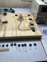
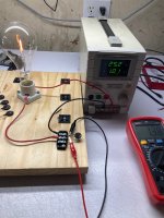
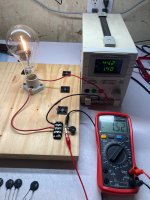
Lol okay, so I went & did it.
A 300W incandescent bulb in series with a 10 Ohm thermistor is just about perfect to draw 1A with 25V DC applied. To draw 1.4A takes 44V.
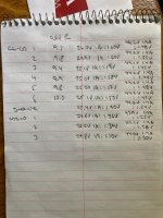
Readings at steady state where the voltage drop across the thermistor is more or less stable* were pretty tight across six Amphenol CL-60 devices. At 1A the drop varied from 1.53V to 1.60V (same in Ohms), at 1.4A it varied from 1.41V to 1.51V (hot resistance of 1.007 Ohms to 1.078 Ohms). There are two clear matched pairs among this group of six, and two outliers.
Three EPCOS NTC 10s were 1.36V, 1.37V, and 1.30V at 1A, and 1.25V, 1.26V, and 1.20V at 1.4A (hot resistance of 0.892, 0.900, and 0.857 Ohms, respectively).
A single green SCK 108 was 1.7V at 1A, and 1.54V at 1.4A (1.1 Ohms hot).
*drifting periodically both up and down by ~10mV, which is about the limit of resolution for this apparattus & this operator.
I'm probably going to pick 4 of the best hot-matched CL-60s to use in the rails of my F5m. Since I care about DC offsets, I'm planning to closely match the thermistors positive rail to negative rail for each channel, with matching across rails a lower priority. My rails will probably be 200mV lower than they would otherwise be with the EPCOS NTC 10s.
A 300W incandescent bulb in series with a 10 Ohm thermistor is just about perfect to draw 1A with 25V DC applied. To draw 1.4A takes 44V.
Readings at steady state where the voltage drop across the thermistor is more or less stable* were pretty tight across six Amphenol CL-60 devices. At 1A the drop varied from 1.53V to 1.60V (same in Ohms), at 1.4A it varied from 1.41V to 1.51V (hot resistance of 1.007 Ohms to 1.078 Ohms). There are two clear matched pairs among this group of six, and two outliers.
Three EPCOS NTC 10s were 1.36V, 1.37V, and 1.30V at 1A, and 1.25V, 1.26V, and 1.20V at 1.4A (hot resistance of 0.892, 0.900, and 0.857 Ohms, respectively).
A single green SCK 108 was 1.7V at 1A, and 1.54V at 1.4A (1.1 Ohms hot).
*drifting periodically both up and down by ~10mV, which is about the limit of resolution for this apparattus & this operator.
I'm probably going to pick 4 of the best hot-matched CL-60s to use in the rails of my F5m. Since I care about DC offsets, I'm planning to closely match the thermistors positive rail to negative rail for each channel, with matching across rails a lower priority. My rails will probably be 200mV lower than they would otherwise be with the EPCOS NTC 10s.
Attachments
And a niche Etsy store was born. 😂
I was hoping there'd be a tell with the resistance at cold for those of us without ready access to 300W incandescent globes, but from your notes it seems to be unrelated. Were they all from the same strip, or just a random collection?
I think I'll just make do with the lucky dip approach and trust that it'll be fine. Not like my ears are a matched pair. 😅
4 of the CL-60s were bought together in a loose bag but who knows what their production relationship was. The NTC 10's were on the same strip.
This would be a painful way to try and make a buck. Honestly this was just satisfying curiosity for me.
This would be a painful way to try and make a buck. Honestly this was just satisfying curiosity for me.
four air coils?
IMHO 2 x LL2751 are sufficient. Replace the serial thermistors in each rail.
For a better price look at the Hammond 196Q2, they're also dual coil:
parallel: 10mH 4A 0.12R
series: 40mH 2A 0.24R
Thanks!
Correction:
For a better price look at the Hammond 196Q2, they're also dual coil:
single: 20mH 2A 0.24R
parallel: 10mH 4A 0.12R
series: 40mH 2A 0.48R
Correction:
For a better price look at the Hammond 196Q2, they're also dual coil:
single: 20mH 2A 0.24R
parallel: 10mH 4A 0.12R
series: 40mH 2A 0.48R
- Home
- Amplifiers
- Pass Labs
- F5m kit