
Why do you need the extra CL-60 at the inlet when you have two on the PSU board?PSU tested and functioning! Reading approximately 26VDC on both + and - with line voltage 121.6VAC.
Thanks again to @poseidonsvoice for taking time to provide a detailed explanation to my question. I leaned something!
--Tom
That reminds me i've been meaning to ask @Nelson Pass why did you design the PSU as CCC (with thermistors at the ends) and not CRCRC? The thermistors act as significant Rs until they heat up. There isn't much discussion in the articles about the PSU, so asking for a friend. 😉Maybe you do need the series resistors in the supply lines, instead of the thermistors, like the standard F5 has.
The resistors will have the same filtering of the supply ripple (with same bias current setting and same capacitors),
whether at start up or later on.
--Tom
Because the CL-60 at mains/live inlet serves a different purpose than the much smaller thermistors on the PSU board.Why do you need the extra CL-60 at the inlet when you have two on the PSU board?
When the power is first turned on, the transformer will draw significant current for the first few mains cycles as the magnetic field builds within the transformer core. The inrush current can reach several hundred ampere, which severely stresses the transformer. Furthermore, to accommodate the high inrush current, the mains fuse used to protect the transformer and connected circuitry must be grossly oversized, which limits the effectiveness of the fuse in the event of a catastrophic fault in the circuit. The CL-60 NTC resistor solves this issue by limiting the inrush current thereby saving your transformer. The amount of current that is drawn is directly correlated with the amount of capacitance in the power supply itself as well as the size of the transformer (in VA). Remember at first turn on, the capacitors are empty so the current draw is very high. If you didn't use a CL-60 or similar thermistor, especially with transformers that are >300VA you will hear a very authoritative growl from the transformer itself as the electromagnetic forces build up.
Best,
Anand.
P.S. I have to give credit where it's due and that is to Tom Christiansen who has a written a treatise on the subject of softstarts.
The inrush current can reach several hundred ampere, which
Not in a typical F5m with a typical F5m transformer. More like half-of-one-hundred amperes. It's easy arithmetic.
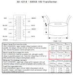
A typical transformer for the F5m might be "Antek AS-4218" which is 400VA and 2 x 18VAC secondaries. As its datasheet shows, the resistance of the copper wire in its primary windings is (7.7V / 3.53A) = 2.18 ohms. So the absolute maximum primary current it can possibly conduct is 120V / 2R18 = 55 amperes. The copper resistance doesn't change when you attach rectifiers and capacitors to the secondary, nor does the copper resistance change as the magnetic field builds within the transformer core.
However, if you move up to 600VA in the Antek transformer line, the AN-6450 has a primary copper resistance of (5.2V / 5.44A) = 0.96 ohms, so the absolute maximum primary current it can possibly conduct is 120V / 0R96 = 126 amperes. Assuming the mains fuse's resistance is zero milliohms, and the on/off switch's resistance is zero milliohms, and the chassis internal mains wiring including connectors is zero milliohms.
_
Attachments
The copper resistance doesn't change when you attach rectifiers and capacitors to the secondary, nor does the copper resistance change as the magnetic field builds within the transformer core.
Thanks MJ, always useful to have additional math and science for corroboration.
I was also going by Tom C's measured data. In example, he stated that an AS-3222, measured 82.5A peak current and the AS-4225 measured 110A. And a 1kvA Plitron measured 200A peak.
Best,
Anand.
Last edited:
Because the CL-60 at mains/live inlet serves a different purpose than the much smaller thermistors on the PSU board.
When the power is first turned on, the transformer will draw significant current for the first few mains cycles as the magnetic field builds within the transformer core. The inrush current can reach several hundred ampere, which severely stresses the transformer. Furthermore, to accommodate the high inrush current, the mains fuse used to protect the transformer and connected circuitry must be grossly oversized, which limits the effectiveness of the fuse in the event of a catastrophic fault in the circuit. The CL-60 NTC resistor solves this issue by limiting the inrush current thereby saving your transformer. The amount of current that is drawn is directly correlated with the amount of capacitance in the power supply itself as well as the size of the transformer (in VA). Remember at first turn on, the capacitors are empty so the current draw is very high. If you didn't use a CL-60 or similar thermistor, especially with transformers that are >300VA you will hear a very authoritative growl from the transformer itself as the electromagnetic forces build up.
Best,
Anand.
P.S. I have to give credit where it's due and that is to Tom Christiansen who has a written a treatise on the subject of softstarts.
The inlet CL-60 makes sense for soft-starting, but why do we need them further down in the supply? Wouldn't Rs of the lowest value needed do the trick?
--Tom
--Tom
The inlet CL-60 makes sense for soft-starting, but why do we need them further down in the supply? Wouldn't Rs of the lowest value needed do the trick?
--Tom
It's anyone's surmise except for Papa himself but I'm going to take a couple wild guesses. First, a couple quotes:
In recreating the F5 for DIY enthusiasts as the F5m I decided to make it even simpler, without
compromising the qualities which made the original popular. - NP
The power Thermistors are used to suppress inrush at turn-on and also as RC filters on the
capacitor banks to lower the noise on the rails seen by the channels. - NP
My guess is that it has to do with:
- cost
- simplicity
- size of the thermistors on the power supply pcb (versus an equivalent resistor)
- size of the power supply pcb board itself (i.e. compact and small)
- ease of build, accessibility of build and finally,
- something different and FUN!


Best,
Anand.
What Anand said. ^^ 😎
The thermistors on the DC side of the PSU are acting as the filtration R. They are cheaper than a resistor bank, and add additional soft-start inrush calming. The configuration in the most recent PCB adds isolated filtration on each channel. Neat!
The thermistors on the DC side of the PSU are acting as the filtration R. They are cheaper than a resistor bank, and add additional soft-start inrush calming. The configuration in the most recent PCB adds isolated filtration on each channel. Neat!
Thanks for clarifying. The PSU is clearly simpler but I wanted to understand what the pros and cons were compared with whats become relatively common in the FW and Pass designs: CRCRC. Thanks for your patience folks.
Again, just asking for a friend. 😉
--Tom
Again, just asking for a friend. 😉
--Tom
Not in a typical F5m with a typical F5m transformer. More like half-of-one-hundred amperes. It's easy arithmetic.
A typical transformer for the F5m might be "Antek AS-4218" which is 400VA and 2 x 18VAC secondaries. As its datasheet shows, the resistance of the copper wire in its primary windings is (7.7V / 3.53A) = 2.18 ohms. So the absolute maximum primary current it can possibly conduct is 120V / 2R18 = 55 amperes. The copper resistance doesn't change when you attach rectifiers and capacitors to the secondary, nor does the copper resistance change as the magnetic field builds within the transformer core.
However, if you move up to 600VA in the Antek transformer line, the AN-6450 has a primary copper resistance of (5.2V / 5.44A) = 0.96 ohms, so the absolute maximum primary current it can possibly conduct is 120V / 0R96 = 126 amperes. Assuming the mains fuse's resistance is zero milliohms, and the on/off switch's resistance is zero milliohms, and the chassis internal mains wiring including connectors is zero milliohms.
_
In rough terms, does the thermistor resistance at ambient temp simply sum with the transformer resistance to give you a new starting current figure that just follows the curve in the thermistor data sheet until you reach minimum resistance? Or is it more complicated than that (most things seem to be)?
Basically I ordered the boards and not the parts kit, and so I'm trying to understand the thermistor choices beyond "seems like most people chose X".
The max temp figures and deratings especially confuse me - is that the temperature they reach at minimum resistance, or the temperature they can stand before performance degrades? Is how hot they get just a matter of how much power they have to dissipate at minimum resistance? Most list a temp of 175C or so, but SG40s say 65C, and I wonder if they're even talking about the same thing. It's further complicated by the fact that the Ametherm data sheets I can find don't seem to be all that consistent in how they present information.
The thermistor is used with AC cap filter which serves as additional RC filter to suppress/block unwanted spikes coming from AC mains. This is commonly seen in SMPS, server power supply, etc. With such low cost part this gives added advantage besides soft start and additional protection.
That is exactly what was confusing me too, but that might have been Papa's point - to struggle with these options to understand the why/if. Other than the stated advantages 6L6 made above, which are around cost / footprint, there does not appear to be any technical advantage to using them versus a fixed resistor (of the appropriate type / size / room temperature) and the CL-60 on the AC inlet, in this application.
--Tom
--Tom
I have two heatsinks, 10"wide, 6"high, 0.25" thick with 30 x1" fins. I think this should be enough for one F5m??
Some of this has been discussed before in this thread. See posts 1,126 and 1,132 by rayma
https://www.diyaudio.com/community/threads/f5m-kit.408290/post-7651383
https://www.diyaudio.com/community/threads/f5m-kit.408290/post-7651451
So it is certainly possible to go with fixed resistors, but it would require quite high wattage resistors in order to handle the inrush current (e.g., note the values rayma provides in the post above for the original F5, which had a fixed resistor, but did have more filter capacitance to deal with), which is the point 6L6 was intimating at. Nelson's design for the F5m PS is a very elegant alternative.
Vinay,I have two heatsinks, 10"wide, 6"high, 0.25" thick with 30 x1" fins. I think this should be enough for one F5m??
Your heatsinks should be good enough for a F5m build with a lower bias point - maybe start from 1.1A bias and see how it goes.
Do you have the PCBs and the parts?
I have one set of PCBs but no parts. I priced out parts on Digikey for enuff components for two, so might go with that. Tho only have boards for one, will have to wait for next PCB availability.
I have bigger heat sinks, about 50% more surface area (6" high x 9" wide x 23x2.25" fins, four of these), so thinking it might worthwhile to make two of these...the old adage what you loose on margins you make in volume.
I have bigger heat sinks, about 50% more surface area (6" high x 9" wide x 23x2.25" fins, four of these), so thinking it might worthwhile to make two of these...the old adage what you loose on margins you make in volume.
@Nelson Pass wrote:
Why, yes, Mr. Pass, yes I am!By now perhaps you are thinking about building this amplifier
Attachments

- Home
- Amplifiers
- Pass Labs
- F5m kit