Got the 4.7ohm thermisters this evening. Desoldered the three 10ohm thermistors on the power supply board and soldered on the 4.7ohm.
Also swapped the black thermal pads for Keratherm 86/82 0.25mm. I'm leaving the bias at 1.7A for now as it's sounds good and temps were steady between 48-50°C.
Back to playing glorious 🎶 music 🎶 again!

Also swapped the black thermal pads for Keratherm 86/82 0.25mm. I'm leaving the bias at 1.7A for now as it's sounds good and temps were steady between 48-50°C.
Back to playing glorious 🎶 music 🎶 again!
Attachments

Just to share and possibly help newer folks (like me) building and biasing this Firstwatt design who maybe read my comment above regarding leaving bias at 1.7A and thought, "Is more bias better?"...I have now dialed my F5m back to closer to 1.6A (0.75V across 0.47ohm resistor). I had noted after about 3 hours of playing music at the original potentiometer(s) bias settingposition, the measured bias had risen up closer to 1.75A and I was now getting 55°C on my heat sinks. Since my house is currently in the low 60's °F for room temperature, I felt I should provide more margin for the heats sinks for warmer room temps that summer will bring. At 1.6A bias, I'm back down to 50°C on the heat sinks of the 4U/300 chassis. I may dial it back further in the future. From a listening point of view, I couldn't tell a difference between 1.7A and 1.6A bias. Both sound wonderful and the high frequencies are exceptional on this amp.
I feel I can't say thank you enough, so "Thank you Papa!" for the wonderful gift of the F5m.

Left to right DMM readings...
Dc offset left [mVDC] / bias left [VDC]/ bias right [VDC] / bias right (second resistor) [VDC] / dc offset right [mVDC]
I feel I can't say thank you enough, so "Thank you Papa!" for the wonderful gift of the F5m.
Left to right DMM readings...
Dc offset left [mVDC] / bias left [VDC]/ bias right [VDC] / bias right (second resistor) [VDC] / dc offset right [mVDC]
Last edited:
Wow! that's great stuff. I must admit I had assumed that such devices only come into play momentarily on start up and temperature wasn't an issue once up and running. Of course for cheapskates like me the third dimension in choosing components is whether you can use what you have already. I'm back where I started and feel ok with 2 CL60's in series for this.Not thrilled with CL-60 inrush limiter in USA/160W Class A First Watt
Same here, unless I had something else on hand. The only weakness is if you wanted to keep turning it off and on....once hot, the time delay feature isn't there....but I don't do that! Worst case you might lose a fuse?
Russellc
Russellc
For the first year or so I had my dual mono F5 with no time delay AT ALL! Just banged it on. Hardly recommended. Still runs fine.
Russellc
Russellc
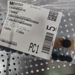
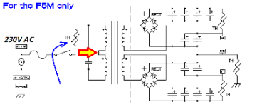
If you're looking for the message in this thread which suggested inrush current limiter disc part numbers, to install in the primary windings of the two Antek transformers which Nelson Pass's .pdf design guide specifically recommends for the F5m, it's post #501. This thumbnail shows one attachment to that post, it may look familiar. The other two ICLs, on the secondary side of the transformer, are not discussed in #501.
_
_
Attachments
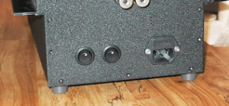
Are those knobs having blue circles that light up? 😯Just to share and possibly help newer folks (like me) building and biasing this Firstwatt design who maybe read my comment above regarding leaving bias at 1.7A and thought, "Is more bias better?"...I have now dialed my F5m back to closer to 1.6A (0.75V across 0.47ohm resistor). I had noted after about 3 hours of playing music at the original potentiometer(s) bias settingposition, the measured bias had risen up closer to 1.75A and I was now getting 55°C on my heat sinks. Since my house is currently in the low 60's °F for room temperature, I felt I should provide more margin for the heats sinks for warmer room temps that summer will bring. At 1.6A bias, I'm back down to 50°C on the heat sinks of the 4U/300 chassis. I may dial it back further in the future. From a listening point of view, I couldn't tell a difference between 1.7A and 1.6A bias. Both sound wonderful and the high frequencies are exceptional on this amp.
I feel I can't say thank you enough, so "Thank you Papa!" for the wonderful gift of the F5m.
View attachment 1289618
Left to right DMM readings...
Dc offset left [mVDC] / bias left [VDC]/ bias right [VDC] / bias right (second resistor) [VDC] / dc offset right [mVDC]
I'm going with a CL-80 (47 ohms) in the primary for my rebuild. I have a second switch I throw after the thermistor squashes the inrush (a few seconds). The second switch simply shorts the thermistor out. Taking that guy out of play after he's done his job. It's silly, dumb, lame, odd, out of the norm, etc... but that simple setup has been reliable for almost twenty years now. No loss of mains voltage and eliminates a hot running part. No additional "soft start" supplemental pcb's / timed relays or anything. And forgetting to hit the switch is no big deal.
Last edited:
Just don't forget to shut that switch off again when you shut down the amp, or else you might start it without the inrush limiters...
I'm thinking someone came up with a simple relay based delay circuit somewhere on this forum... I may have to look for it.
I'm thinking someone came up with a simple relay based delay circuit somewhere on this forum... I may have to look for it.
After twenty years of practice I've gotten pretty good at turning off both... but ya you're right.don't forget to shut that switch off
Attachments
That's a really simple solution @william2001 . Made me think of what could be done to avoid the one risk...
What if the switch on the inrush thermister was momentary, and when it's pressed in, current flows through the thermister, but once released, the switch automatically returns to the "bypassed" state taking the thermister out of the circuit, and then, you make a safety mechanism (think protected switch) that will only allow you access to the on/off power switch if the momentary switch is pressed in (flipping up the guard depresses the momentary "un-bypass" switch). Or maybe just make the gaurd position itself the momentary switch that diverts current through the thermister. I might try this just for fun after being inspired by your approach. It's a bit of a bunny trail off topic, however, I liked the simplicity of your approach.
Of course, there's Mark's H9kpgx, which seems like an ideal solution as it adds the power switching up front along with the inrush bypass circuit. I plan to place an order soon and will be sure to get extras. I have been holding off on the order to add a few other gerbers to save on shipping.
https://www.diyaudio.com/community/...ains-relay-includes-soft-start-h9kpxg.354971/
Has anyone built both the F5m and the AlephJ, and tried them using the same sources and speakers? If so, can you offer an opinion on what you think about the differences in sound? Any differences using single ended input to differential?
Thanks!
Thanks!
The Aleph J has a slightly more focused center image and perhaps a bit more soundstage depth. That’s probably due to the xlr configuration. The F5M is more detailed, the bass is punchier, and of course it’s got more power. These are what I’ve found so far.
Thanks, that's helpful! I'm sure the higher detail is a derivative of the circuit simplicity. And although I have not built the F5m, the Aleph J (I have 2 in bi-amp) has a stunning stereo image and depth. Perhaps better than anything I've heard.
With regards to power - what is the power output of the F5m? I did not see it in the Pass document at the start of this thread.
With regards to power - what is the power output of the F5m? I did not see it in the Pass document at the start of this thread.
Power= just those two graphs on page 2. Power is typically rated at 1% THD, 1kHz, so just follow the line to see where that falls for the 4 and 8 ohm loads.
I am currently listening to my F5m with a recently completed upgrade to the power supply filters on each channel. Prior to this I was listening to a version of the Aleph J built with the simplified SS PCBs. And before that my F6 Diamond with the CineMag transformers..
All three of these amps sound more similar than different. They are all using high transconductance FETs in their output stage; some more so than others. My F5m and Aleph J SS now have very similar power supplies - a single transformer driving an enhanced Universal PS with separate motor run cap filtering in each channel.
The Aleph J has better rejection of the 120 Hz hum from the rectifiers. Once its motor run caps were in place, the imaging and soundstage were the equal of my best dual-mono build (the F6). Transparency was a revelation on some recordings. I needed extra time to find the right voicing to get just the right spectral balance. Obscure experimentation with Aleph coupling caps and tantalum film resistors, etc., nobody cares. But it became an amazing amp that I would happily live with indefinitely.
I have written about the F5m in the other thread, and it keeps sounding better. The motor run caps did their trick for the imaging. Instruments are fully detached from my speakers. There is a very slight residual 120 Hz hum; not something that bothers me when I’m in the room, just a nag at my OCD. Having said that, the F5m is slightly more laid back in its presentation. Bass extension is impressive, though it doesn’t call attention to itself. The bass of the Aleph J became a feature on some recordings. The F5m continues to excel with musical flow
Of the three amps mentioned, my F5m is using somewhat more conventional FETS. The FQA28N15 and IXTQ26P20P are a good pairing.
My recommendation is to build both or all three.
Hi, that's a great summary. I dug up the Aleph J manual from NP, and it says: "25 watts @ 1% THD 1KHz" into 8 ohms. According to the graph for the F5m, that's nearly identical. Someone said "more power" than Aleph J, but not sure what that means as the F5m graph appears to be the same.
You mentioned the FQA28N15 - this is the driver I am using on both my Aleph J's. I had the spec parts in there (IRFP240) and decided to try the FQA28N15. I liked them better, they sounded more musical (IMO) so bought 4 tubes. Too bad they're going to stop production.
I never tried a motor run cap. What capacitance? Initially I built the DIY stores' power supply boards, then decided to build my own board (am a PCB designer) and used the Hammond 159ZL chokes + a 50milliohm series resistor. 30kF before and 60kF after. It really brought out the sound. It's like crack for the soul!
I think I will build the F5m just because of the simplicity, and I'm intrigued by the feedback and comments in the thread. And, I've got a couple hundred 2SK170BL's so this is a good opportunity too use a couple.
- Home
- Amplifiers
- Pass Labs
- F5m kit