Helpful yes, thank you. I'll want to try your suggestions on some test metal before attempting it on another chassis.I am far from an expert with the metal work but I have successfully performed the drill and tap routine with dozens of holes without breaking anything over the years (knock on wood).. So here's my basic routine and tools used.. I think the quality of the drill and tap itself is important. I got those at MSC, part #'s shown (for M3). I always center punch first so that the drill bit doesn't wander. Cutting fluid - I always use Tap Magic for any drilling and tapping operation. I run the tap by hand with the T Handle. Go slow and back out when you feel resistance. It's a slow and patient back and forth kinda thing, cutting the threads. Keep the tap clean by brushing away the excess shavings that causes the binding. I have an old Delta drill press I bought cheap at a garage sale a long time ago. That was definitely worth it looking back now. Hope something there helps..
Good news is that Plan B worked just fine. By pure luck, the two center-line holes from the botched attempt were the only ones I successfully drilled and tapped, and they are in the right position when the HS is flipped around. It was a little tricky to install the through bolts, but not much of a setback in the end. Not as pretty as ModuShop would have done it, but it has more personality, right?
Attachments
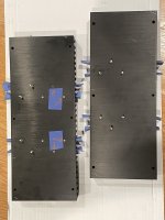

Interesting. I don't reacall how the heatsink frames were configured for my ACAs (I could look, but that would involve using a screwdriver ...). I just finished installing one side, and found it relatively easy to remove the frame temporarily.From post #1 it looks like current production 3U/300 Mini Dissipante chassis now use the "picture frame" style chassis mounts for the heat sinks. This is the same type used in the 4U 400 monoblocks (second picture). In the past the 3U/300 had a top and bottom rail (first picture), as was used in the ACA chassis and these were first bolted to the heat sinks. The order of assembly seems to differ for the picture frames; at least in my hands the picture frame has to first be mounted to the baseplate with countersunk flat-head screws, then later the heat sinks are bolted to the frames.
Also the Philips-style screws that hold the front plate on are tricky to access in a chassis full of trafos & PSUs. The Japanese make these wonderful right-angle screwdrivers of extremely low profile that make this job at least possible, if not easy.
I really do like those Japanese screwdrivers! Source?
Attachments
Oh, interesting, your picture frame mounts to the base plate differently from the one on the monoblocks. Yours is much easier to access.
ANEX low profile screwdrivers
ANEX low profile screwdrivers
But still definitely need a set of those screwdrivers.Yours is much easier to access.
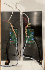
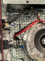
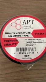
All wired up! But no place to go just yet.I remembered vaguely that the insulating strips in some of the F5M kits were not insulating, and I just confirmed that my strips conduct. So unless Amazon can ship me some Polyamid tape tomorrow, no sound test this weekend -- bummer!
Attachments
It is 100% your call / decision, but... you have brand new anodized heatsinks.
So... if you'd like... you could... install the insulators and run a quick resistance check to decide if you want/need to get new insulators or not ... short or long term.
If you need certainty... definitely wait for new ones. If you know how to check, and you don't mind a few minutes work with a small chance that you may want/need to change them anyway... you can give the ones in the kit a try.
So I measured about 135 ohms from the transistor backs to the chassis. I honestly don't know whether that's acceptable.
Were you measuring from the center pin of the MOSFETs to one of the mounting holes / bare metal on the chassis? PSU disconnected from amp board(s)?
You certainly can run it while your waiting for the proper insulators - it should behave
as if there was a 135 ohm load at the output....
as if there was a 135 ohm load at the output....
I measured from the metal case of the FET, which is slightly exposed on the front, to the bare chassis. Yes, this was prior to wiring up PSU. I subsequently loosened both of the devices and insulated them with plastic cards to confirm that there was no other conductive path.Were you measuring from the center pin of the MOSFETs to one of the mounting holes / bare metal on the chassis? PSU disconnected from amp board(s)?
Attachments
Sweet -- thank you!You certainly can run it while your waiting for the proper insulators - it should behave
as if there was a 135 ohm load at the output....
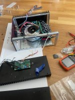
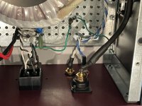
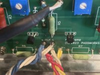
They're connected to the cable shields for the audio inputs (twisted, shielded quad conductor).On post 25, What’s the other green wire I see connected to your chassis ground? I see a similar one on the other side of the amplifier as well where your electrostatic shield (purple wire) from your transformer is connected.
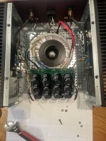
Amazon came through with the polyimide tape, and I isolated all four power mosfets without having to disassemble too much.
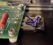
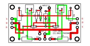
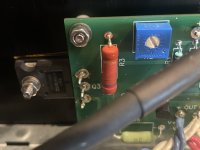
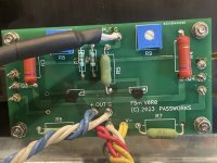
On to biasing. Left channel behaving as expected, however on the right channel, the voltage drops across R6 and R7 never exceed 80mV with the pots fully clockwise. Anyone have thoughts on how to troubleshoot?
On to biasing. Left channel behaving as expected, however on the right channel, the voltage drops across R6 and R7 never exceed 80mV with the pots fully clockwise. Anyone have thoughts on how to troubleshoot?
Attachments
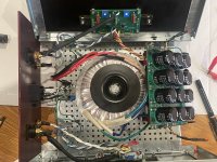
First, post pictures of the board and of the whole amplifier for the big picture.
For measurements, measure the PS voltages on the board to make sure that they are correct.
With a voltmeter at each mosfet G and S pins, turn the corresponding pot. Does the voltage change when the pot is turned? What is the maximum voltage?
For measurements, measure the PS voltages on the board to make sure that they are correct.
With a voltmeter at each mosfet G and S pins, turn the corresponding pot. Does the voltage change when the pot is turned? What is the maximum voltage?
Attachments
Polyimide (Kapton) tape is a thermal insulator not conductor. Probably better to use thermal pads meant for the task.
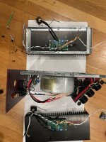
@Ben Mah here are the measurements you suggested making.First, post pictures of the board and of the whole amplifier for the big picture.
For measurements, measure the PS voltages on the board to make sure that they are correct.
With a voltmeter at each mosfet G and S pins, turn the corresponding pot. Does the voltage change when the pot is turned? What is the maximum voltage?
V+ 25.7v
V- -25.6v
Q3G 25.7 to 21.8v (CCW to CW)
Q3S 25.8 to 25.6v
Q4G -25.8 to -22.4
Q4S -25.7 to -25.6
While I'm still curious to hear what you make of them, unfortunately I created two bigger problems for myself. First, I blew out the (previously working) left channel while attempting to gather a comparitive data set; and then I shorted something while attempting to measure the voltage behavior across R5 on the right channel. So I'm going to have to pull both boards and test every component. I'm bummed.
Attachments

Last edited:
Yeah, this was the best I could find with next-day delivery -- good enough until the parts from DIY Audio get here.Polyimide (Kapton) tape is a thermal insulator not conductor. Probably better to use thermal pads meant for the task.
I wouldn't be cranking on the pots willy nilly, that's sure to burn something up. Those pots are like faucets controlling the current through the power fets. You open one a little bit, then the other one a little bit, and keep repeating. It's a balancing act where you are equalizing how much "work" each device is doing. You go back and forth adjusting the two pots slowly and carefully, small bites at a time, watching the current through the source resistors (R6,R7) with your voltmeter to keep things more or less equalized as we hone in to that final setting of desired Iq and low DC offset at the output. So at minimum you have two voltmeters, one watching the source resistor voltage (use ohm's law to calculate current) and the other watching the DC offset voltage (always aiming for zero). These are your "eyes" so that you can keep track of what's going on as you adjust this thing. I would want to see Keratherm pads and some nice fat washers on those ouputs. We want as much thermal transfer as possible to the 'sinks.
When I'm measuring on a live circuit I will typically use small clip leads on the component leads before power up to prevent slippage, blown parts, followed by sadness and disappointment...
When I'm measuring on a live circuit I will typically use small clip leads on the component leads before power up to prevent slippage, blown parts, followed by sadness and disappointment...
Last edited:
- Home
- Amplifiers
- Pass Labs
- F5M build w/ Mini Disspante 3U/300