I think you want some capacitance across the 100 ohm feedback resistor.
Start with 1 nF.
😎
I'll try it tomorrow
Thank's
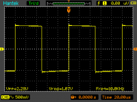
Input looks fairly OK if the picture is taken under same conditions - func. gen. loaded by amp's input.
Ups, sorry.
That signal generator to scope direct without loaded by amp input 😱
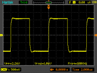
this one loaded with amp input
Try first the nr. 3 (add 330R in series with 240R at the gates of MOSFETs) - just to eliminate the last thing first... 😀
Well this one is "heavy" task, because i had to pull the amp pcb off from heatsink
i'll try it after add some capacitance at feedback first 🙂
Attachments
Tempest in a teapot 😉
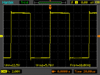
Your amp did just what it's supposed to do - overshot in, overshot out...
Your amp did just what it's supposed to do - overshot in, overshot out...
Tempest in a teapot 😉
Your amp did just what it's supposed to do - overshot in, overshot out...
Yes, that slight overshoot but not much compare than output
Here's the report :
1. Remove one of 150R (75R sum) at feedback ==> no luck here
2. Change 243R gate stopper to 681R ==> same, no luck
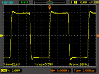
3. Put capacitance as Nelson Pass says at 150R (50R sum) ==> compress the overshoot a bit (try to lower it to 200pF and then 100pF, nothing change)
4. Add a bypass caps at PCB Amp (10uF with 100nF) ==> compress overshoot a bit
Here the result (combination no 3 & 4)
Thank's (Juma and Nelson Pass) for all support

Attachments
Hi Juma
I like your amp design !
Just got to the end of the thread...
...with the world's s l o w e s t internet...
...Phew !
1 question...
...The thermistor.
I see where it is in the schematic...
...I see people mount it 'hovering near' an OP device ( not a metal-tab one, on sink ).
I dunno if I'm being thick here ( probably )...
...but, What does it do ?
You obviously wouldn't have it in your schematic if you thought it wasn't needed...
...one builder didn't fit it...
...I guess they just fitted a 'suitable' resistor, or re-calced the parallel 2.2k etc.
Any explanation of this function would be most helpfull.
People seem to have enjoyed this amp very much...
...great work !
Cheers.
Si.
...
I dunno if I'm being thick here ( probably )...
...but, What does it do ?...
Not thick - just plain lazy... 😀
Read the F5 manual/article at the firstwatt.com
NTCs are there to thermally compensate for the vertical MOSFETs' tendency to increase channel current with temperature.
With biiiiig heatsinks and enough time at hand to wait for thermal equilibrium to be established (an hour or so), you might decide that you can live without NTCs in this amp...
Hi Juma
Not at all...
...cheeky !
( lazy, I mean...def. thick ! )
I tried downloading the F5 manual THREE times at 1stwhat?...
...it ain't happening on this computer, is all I can say.
I see...
...thanks...
...short & sweet ( just like the amp, by the sound of things ! )
I figured it was for something like this of course.
It just seemed to me, with 'loose coupling' ie. no metal-tab...
...to be more of a 'randomizer' than a 'stabilizer' ! ( probably just me though ).
I see the F5 similarity.
But don't really see this as anything like an F5.
Loads of bits taken out...
...& regulated supply put in.
Reminds me more of some kind of Hitachi or Motorola application notes, I vaugely remember from the 70s' or 80s'.
biiiiig is better !
Cheers.
Si.
Not wishing to appear LAZY...We made a start at the 'crack of dawn' today.
Hi Juma
I'm still thinking your amp looks pretty groovy.
So not wishing to appear TOO lazy...
...made a start today...by erasing all the text from the schematic.
( no need to be alarmed...we do that on all our new projects here )
WOW ! it's just so mind-blowingly MINIMAL !
C O O L !
Cheers.
😀
Si.
Here it is after the erasing work.
Attachments
Actually, we can shave this version of F5 a bit more and still make it work nicely.
If we accept lower power (10W RMS @ 8 Ohms) and use the lower voltage in power supply (+/-15V) we can bias the MOSFETs near the zero tempco point (about 0.6A) which will get us rid of NTCs and with carefully chosen JFETs' drain resistors we can avoid trimming pots.
For lower power 2 pairs of output MOSFETs will be OK.
Attachments
" Jumpin' junction count Comissioner Gordon !...
...That joker Juma will have the Gotham City semi-conductor industry on it's knees by January ! "
" Exactly Bat-Ears !...
...You and the Boy-Wonder are the Gotham high-end audio industries last hope...
...we can't allow this kind of musical minimalism on the streets ! "
" Robin !...To the Toshiba-mobile ! "
" Yes Bat-Ears ! "
Hi Juma
I like your schematic by the way !
If I had 22-bit digits ( instead of 20 ), I could count ALL the parts in 1 Byte ( including the extra thumbs ! ), and NOT loose count...
...N I C E !
Could be possible to loose 1 of those feedback resistors, I guess; and replace with 1 BIGGIE !
I know people get all 'steamed up' about 'mythical inductance' here...
...any objections to 1 B I G chunky 25R wire-wound ?
Mmmm...
I like the parts minimalism Juma...
...but I rec. you 'had it nailed' the 1st time, with the 6 little Toshey's you used.
( I wanted 8, when I first looked; but hey, dunno why really )
Your original schematic looks 'good to go' to me...
...especially since The Space Egg Corp. parts-stash, already has most of the bits & bobs for the amp !!!
The transformer we have BTW is a 225 Watt 18-0-18 donut...
...could get a second one of these as well; I know they like 'em BIG round these parts.
( seems like enough Watt-not's to me though; bout 100 needed )
Loads of other parts here as well.
Main missing items being the IRF's & a couple of 2SJ74's ( got some 2SK170's ).
As for the whole NTC thermistor buisiness...
...We have some quite unusual heatsinks here...
...been in 'cold storage' for a few years; waiting for 'the perfect amp' !
4 of 'em; strange-shape, actualy intended for forced-air cooling...
...although they might do the job with just convection ( prefered ).
( we have an in-audible Akasa 120mm ball-bearing 'balanced' PC fan here, as well, N I C E ! )
The data I have for the heatsinks, is all for forced-air apps...
...so unsure of the convection specs.
They do look a 'bit' small for you boys round here...
...but I rec. I might JUST get away with it; if the case is designed around them, in a good way.
The other interesting part I have, is a whole bunch of 220R wire-wound 70s' instrumentation pots ( N I C E ! they don't make 'em like THAT any more ! ).
I know pots send shivers down the spines of yer average 'audiophool'...
...but hey, these dudes is q u a l i t y.
Perhaps a few K's across 'em for a bit of 'ultimate stability'.
Anyhow, all good.
Can't really live with 10 Watts...
...I dunno though...
...Could we ?...
...Mmmm...?
That 'IDEAL' operating point you mentioned, does sound interesting though...
...we aint got a 15-0-15 though.
I guess you originaly went for what you did; cos of your 'lowish' Ohm speakers.
Cheers.
Si.
Hi Juma
I am getting a few of the parts I don't have, to build your amp.
I have a number of 2SK170-BL's, across the full spec. range.
I need to get some 2SJ74-BL's to go with them.
What would your prefered Idss be for the input devices ?
I possibly have a choice here.
Cheers.
Si.
I am getting a few of the parts I don't have, to build your amp.
I have a number of 2SK170-BL's, across the full spec. range.
I need to get some 2SJ74-BL's to go with them.
What would your prefered Idss be for the input devices ?
I possibly have a choice here.
Cheers.
Si.
Anywhere in BL range id OK - practical differences are negligible. If you can choose, 8-10mA is a choice that's narrow enough.
Juma, would you say that your F5 with 2SK2013/2SJ313 is the most sonically pleasing amp that you've built as yet?
In this category of amps (Class A, 20W, 4 Ohms drive capability, voltage gain>0dB) I found nothing that I like more...
Last edited:
In this category of amps (Class A, 20W, 4 Ohms drive capability, voltage gain>0dB) I found nothing that I like more...
Thanks Juma. Now that is saying a lot in favour of your amp. O.K. I have all the components except heatsinks, so maybe I should give this a go. But I am also attracted to Nelson's ACA in view of its tube-like sound and lower Pd😕
... in favour of your amp. ...
It is still Mr. Pass' amp. I just used different output devices and excluded the current limiting protection circuit.
True, the topology and particularly the feedback is from Mr.Pass but you took it steps ahead by using then available better output devices. I may go with 4 pairs of Output devices.
what is different from the Pass BA-3 frontend ?
looking at schematics I see only minor difernces
I really can't figure out why this is a poweramp, and the BA-3 only a gain/driver stage
btw, some time ago I worked hard to find good TO-220 devices for the F5
maybe some of them could be good ?
or is it all down to these special Toshiba devices ?
looking at schematics I see only minor difernces
I really can't figure out why this is a poweramp, and the BA-3 only a gain/driver stage
btw, some time ago I worked hard to find good TO-220 devices for the F5
maybe some of them could be good ?
or is it all down to these special Toshiba devices ?
maybe this pair ... IRFZ14 / IRF9Z14 ?
http://docs-europe.electrocomponents.com/webdocs/0791/0900766b807912c5.pdf
http://docs-europe.electrocomponents.com/webdocs/0791/0900766b8079172b.pdf
http://docs-europe.electrocomponents.com/webdocs/0791/0900766b807912c5.pdf
http://docs-europe.electrocomponents.com/webdocs/0791/0900766b8079172b.pdf
- Status
- Not open for further replies.
- Home
- Amplifiers
- Pass Labs
- F5 with 2SK2013/2SJ313