Hi,
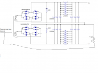
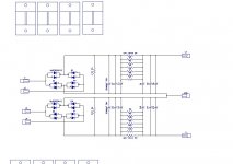
1. can you please let me know if there is anything wrong with attached circuit. This is for f5 Turbo. Anything additional required before connecting to ground?
cap - each 22000uf, resistor values mentioned in attachment.
2. Assuming both left and right channel can be connected to same PSU unit shown in attachment without any issue?.
3. Have another question on transformer
I have one toroidal 800VA
Two primary 0-120, 0-120
secondaries 0-24(400VA), 0-24(400VA)
There is one green wire that says "shield", does anyone know what is shield for?
Thankyou for looking.
Attachments
Last edited:
f5 Turbo power supply?
Hi,
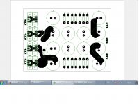
Attached is just f5 power supply with MUR3020WTG diodes. I have made board since i wanted to use 12 caps 22000uf.
Anyone who has experience with PCB designing can please provide you inputs if you see anything wrong. Please check images.
Thank you in advance.
Hi,
Attached is just f5 power supply with MUR3020WTG diodes. I have made board since i wanted to use 12 caps 22000uf.
Anyone who has experience with PCB designing can please provide you inputs if you see anything wrong. Please check images.
Thank you in advance.
Attachments
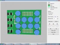

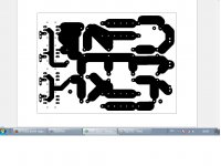
Those traces look extremely thin.
Charging currents tend to be very high and you don't want too much loss on the board (some is inevitable).
We normally try to keep track width at least 200 mil or more in this kind of all-in-one board. Think of using more planar areas and doubling tracks where possible on both sides of the board.
Similarly for the diode boards, run the inputs and outputs on different layers, or the negative and positive supplies. You will have more board area to work with.
Also recommend using a stop mask on the copper so you can solder a bus bar, in case the tracks cannot be widened further. For this the tracks need to run straight instead of this convoluted manner.
Post3.
Do not take any audio voltage references back to the PSU point where there are enormous charging pulses from the rectifiers. NEVER !
Do not take any audio voltage references back to the PSU point where there are enormous charging pulses from the rectifiers. NEVER !
Thankyou AJT, Sangram and Andrew
I have already invested in hardware(Nelson Pass PSU circuit) so i'll stick to that.
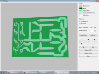
I have widened tracks.
small ones are 8mm thick
Big ones are 15mm thick
is that fine?
If you look at images, is it an issue how close tracks are?
If yes i'll reduce thickness or redraw them.
Thankyou for your inputs.
I have already invested in hardware(Nelson Pass PSU circuit) so i'll stick to that.
I have widened tracks.
small ones are 8mm thick
Big ones are 15mm thick
is that fine?
If you look at images, is it an issue how close tracks are?
If yes i'll reduce thickness or redraw them.
Thankyou for your inputs.
Attachments
Apart from question in my previous post, this is for F5Turbo V2 32V
What length heat sinks are you using for PSU diodes Length - 12.5mm or 25.4 mm and how hot does it get.
What length heat sinks are you using for PSU diodes Length - 12.5mm or 25.4 mm and how hot does it get.
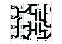
change in layout
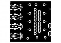
Due to space constraint there was need to reduce size so i have to go for another layout. After going through few posts its recommended to use one side as ground so doing that as well. Attaching new layout please let me know if you see any major flaw.
All tracks are 10mm wide and the ones that are 5mm wide are laid on both sides of pcb.
Is using copper pour(to have wide copper paths, non uniform shapes) instead of traces good idea(referring to top side)?
transformer has 4 wires 0-24,0-24
Attachments
Last edited:
when using a capacitor as smoothing one brings the input to the cap lead as near the capacitor body as possible. One then takes the output from the cap lead as near as possible to the cap body.
The effect of this is that the internal lead inductance is shortened and the smoothing performance is better, particularly at the higher frequencies.
If one uses multiple capacitors to form a capacitor bank, one must do the same.
Putting a capacitor out on a long trace along which the current must flow in and then out increases the inductance and could potentially ruin the higher frequency performance.
Redesign to minimise the trace impedances.
If you're trying to squeeze 12 caps onto a small PCB like that, I would suggest not using the resistor pads at all. They are going to consume a lot of space and are forcing you to orient caps in the L shape and the squiggly tracks.
When we face similar situations we basically solder the resistors under the board, directly to the caps' pads. This will help to line up your ducks, so to speak. For even tighter spaces you should forgo the board entirely and use point to point wiring. A PCB is not strictly needed for simple circuits like this.
As to your other question, I usually bolt the diodes directly to the case floor. You can achieve the same mounting method if you use a 90 degree aluminum angle and bolt the diodes to it. Obviously the diodes will be mounted to the bottom of the board if you choose this method.
Thankyou Andrew and Sangram for your valuable feedback. I'll incorporate your suggestions and get back.
Only reason to stick to PCB is to have components well organized. I'll think about it.
Only reason to stick to PCB is to have components well organized. I'll think about it.
Have one more question
How much capacitance is good, PSU page says 80,000uf or more(so i added 12 22,000uf) ?
what is the benefit of adding more capacitors, i can add more but is it worth the price that goes into caps?
How much capacitance is good, PSU page says 80,000uf or more(so i added 12 22,000uf) ?
what is the benefit of adding more capacitors, i can add more but is it worth the price that goes into caps?
I use and recommend to others ±20mF for an 8ohms capable ClassAB amplifier.
That lets me set the passive input filter of the Power Amplifier to 1.6Hz and ensures that all of the audio bandwidth is passed through to the speaker/s.
If you use 4ohms speakers, then I recommend you use ±40mF for each amplifier that has to drive the full audio bandwidth.
My most recent stereo amplifier has two 8ohms channels fed from a common supply. There I used three pairs of 15mF capacitors to give an effective ±22500uF per 8ohms channel.
ClassA requirements are different.
Last edited:
what is the benefit of adding more capacitors, i can add more but is it worth the price that goes into caps?
Yes, more capacitance is usually better - you get lower PSU ripple and some of this may show up in measurements. However there are some caveats.
You have to remember that caps are charged by the power transformer and diodes. In Class A amplifier they also provide the standing current, which means that there is a balance that is to be achieved between the three elements. Mindlessly increasing cap banks without examining the capability of the other two, or the demands of the circuit being powered, is a waste.
My usual rule of thumb (others' opinion may differ) is to use about 100kuF for every ampere of bias current. Since it is difficult to find specs for the products manufactured/locally available in India, I usually add a margin of error for these products.
This means a typical Class A Build biased at 4A (2A per channel) ends up with approximately 0.5F of capacitance. I think much more than that would be overkill, and you can downsize by a bit without losing much - if any - performance.
My usual rule of thumb (others' opinion may differ) is to use about 100kuF for every ampere of bias current.
This means a typical Class A Build biased at 4A (2A per channel) ends up with approximately 0.5F of capacitance. I think much more than that would be overkill, and you can downsize by a bit without losing much - if any - performance.
Since i can't determine bias upfront does it has to be like account for maximum bias?
I am building F5Turbo V2 "art_f5_turbo.pdf"
32V DC
2 pair MOSFET per channel
800VA Toroidal transformer with 4 wires at secondary 0-24, 0-24
I have 22000uf caps, how much should i use, you have seen the circuit in my earlier post at present i am using 12 caps, adding ones in parallel makes 132000uf.
Hi
In the case of the F5 running off 32V rails, power output is 50W and needs 1.8A per channel if you use the calculations provided in the document and plan for all of that power in Class A. More is helpful, but not strictly necessary. Less is also fine, and the amp works well with as little as 1.2A.
Anyway for 3.6A of bias you would need (if using my thumbrule) 360kuF of capacitance. I would personally not build with less than 300kuF, though I've seen a lot of builds with much, much less so it might be okay. Just using the factory F5 as an example, it uses 8x 15kuF caps for 2.6A of standing current so that is about 46kuF per ampere of bias. Which makes your selection adequate.
However I don't know where you got your total cap figure from. You said you had 12x 22kuF caps, that should be 264k not 132k.
However I don't know where you got your total cap figure from. You said you had 12x 22kuF caps, that should be 264k not 132k.
I meant 132k uF on + and same on - side.
Hi,
1. can you please let me know if there is anything wrong with attached circuit. This is for f5 Turbo. Anything additional required before connecting to ground?
cap - each 22000uf, resistor values mentioned in attachment.
2. Assuming both left and right channel can be connected to same PSU unit shown in attachment without any issue?.
3. Have another question on transformer
I have one toroidal 800VA
Two primary 0-120, 0-120
secondaries 0-24(400VA), 0-24(400VA)
There is one green wire that says "shield", does anyone know what is shield for?
Thankyou for looking.
The shield is likely between the primary and secondary windings. It is normally connected to earth. Functionally the shield reduces the capacitive coupling between the primary and secondary and thus reduces the mains power high frequency "hash" that would otherwise be coupled to the secondary winding.
regards,
Rick
Thankyou
- Status
- Not open for further replies.
- Home
- Amplifiers
- Power Supplies
- f5 Turbo power supply