Toecutter, it is great to see this progress. Keep up the great work, the results are better with each revision. Well done and thanks for your work.
I should be able to load the psu and check diode temps Mon or Tues.
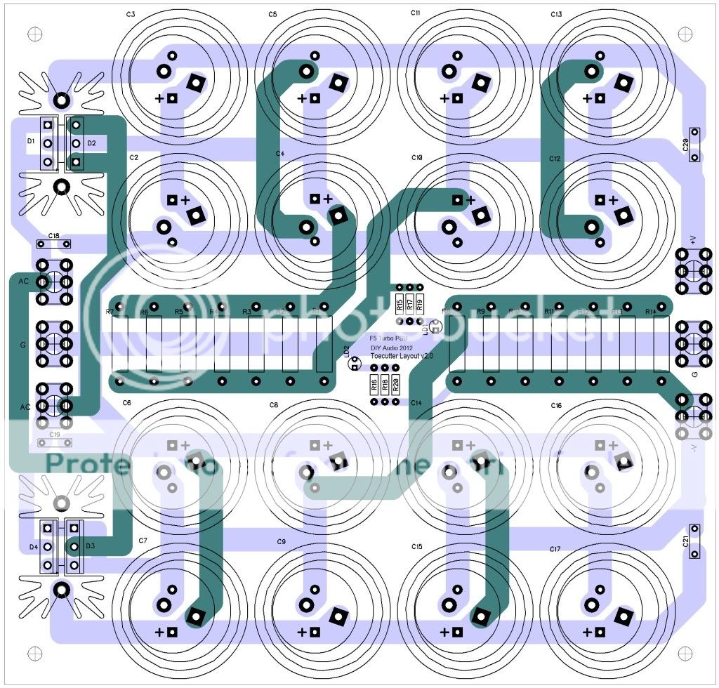
I did have to change the Phoenix connectors to allow for larger wire but I see you have revised that.
I did have to change the Phoenix connectors to allow for larger wire but I see you have revised that.
Toecutter, it is great to see this progress. Keep up the great work, the results are better with each revision. Well done and thanks for your work.
With the connections on both ends of the output boards, you can put an N or P board on either side and still have a short connection to the power supply. Also in a monster Monoblock you could have 2 N type or 2 P type boards daisy chained together on each side.
And the new input board with a pair of input circuits makes a 2ch amp easy, as well as a balanced monoblock.
Or snap it in two for a regular monoblock.
Last edited:
Ok, had some extra time today so I got some temp readings on the PSU board.
With a 5A load at 32.6v the rectifier heatsink settled at 134F @74.5F Ambient
With a 8A load at 31.4v the rectifier heatsink settled at 180F @75.5F Ambient
The cap closest to the heatsink and .47 resistors was at 107F
The PSU is mounted in the enclosure, so there was little air movement. I have tunnel heatsinks with very quiet fans that will be sharing the space, so I'm sure the air movement will make a difference.
I am however wondering if it might be worthwhile looking into larger sinks for the rectifiers.
This was with only one side loaded as I only have one dynamic load. The next step will be using some large resistors to load down both sides.
Might i make two suggestions. Put the diodes at the back of the PSU board like the DCB1 which will allow for easy mounting to a separate small heat sink. If this causes connection problems, put two diodes to each side and the sinks can flank the psu board.
WHAT? - new F5T pcbs?
Did I just waste two months waiting for these pcbs?
The dimensions already changed three times back in Feb., we finally settled for something, you had prototypes made, and NOW (!) you want to go "universal". Universal is what Peter. D. does, makes them miniature and there is a big GB within a month with ton of people who know they can run thick wires and place the output fets in ANY location taht suits their design.
I have small fan-cooled sinks and after your last change I played for hours figuring out how to fit everything based on your 70x70mm (input) and 35x50 (single output) dims. Can I still count on those or should I pursue a different venue? Where are all those people who were attending this thread back in Feb.?
i already let Andy know but for the record:
For me please:
2 input stage boards (70x70mm)
8 single fet output boards (35x50mm),
and please try to make the dimensions stick. no more changes pls Thx.
---------------
Now, if you guys would get past sharing your heatsink designs (everybody's different, Ok, so no details pls..):
Is there some interest maybe in discussing getting matched fets? at least P-to-P and N-to-N matched and then P-to-N side will be left to the trimmer?
Did I just waste two months waiting for these pcbs?
The dimensions already changed three times back in Feb., we finally settled for something, you had prototypes made, and NOW (!) you want to go "universal". Universal is what Peter. D. does, makes them miniature and there is a big GB within a month with ton of people who know they can run thick wires and place the output fets in ANY location taht suits their design.
I have small fan-cooled sinks and after your last change I played for hours figuring out how to fit everything based on your 70x70mm (input) and 35x50 (single output) dims. Can I still count on those or should I pursue a different venue? Where are all those people who were attending this thread back in Feb.?
Yeah it's a bit confusing at the moment , Too much smoke I guess , could be worst , yes , very much so ...
🙁
🙁
What speaker demands a continuous 5Adc from the amplifier?.......................................I got some temp readings on the PSU board.
With a 5A load at 32.6v the rectifier heatsink settled at 134F @74.5F Ambient
...............................................
I am however wondering if it might be worthwhile looking into larger sinks for the rectifiers..............................
V3 could have 8A of draw at all times, even using dual mono supplies, correct? The dodes can operate at mich higher temps. The numbers imix had translate to about 85C, which is well within their ability to continue their work, even at high current levels. V3 will almost certainly require dual mono supplies. As for layout, i must say that i prefer TeaBags version to the current one. Just opinion, though.
So, Imix really means PSU rectifiers, not the rectifiers parallel to the source resistors?
If Imix is running each half of the F5T @ 4A of bias for a total monoblock bias of 8A then I consider Imix only option is to run true monobloc. Any attempt to pull 16A of stereo bias would overwhelm even the biggest of chassis dissipation abilities.
Sorry for my earlier intrusion. I just did not believe the PSU reference.
they only seem to go to about ~60mm tall.
1.65" wide heatsinks that mount diodes on both sides go up to 2.5" height.
e.g. Wakefield 657 or Ohmite F/R series, ~4.25 C/W natural convection at 25C above ambient.
And even then, trouble is to locate a vendor that still carries taller than 2 inches.
On the other hand, try finding a source for Wakefield 256 :
256,260 Heat Sinks Wakefield Engineering PDFs òåõíè÷åñêàÿ äîêóìåíòàöèÿ 256,260 Heat Sinks îïèñàíèå ñêà÷àòü 256,260_Heat_Sinks.pdf Wakefield Engineering PDFs datasheets datasheet data sheets 256,260 Heat Sinks Wakefield Engineering PDFs
(see pics of my Pumpkin build
 )
)😉
If you are referring to me
I am still hear and watching
To me PSU board has far too many tracks crossing over to many bends and one to many layers.
I may get a chance to go balanced in the next week and after that I will start on proper (45 or more V rails) Turbo.
But that will have proper buss bar on output.....
Still supply board is going to be the same as one I posted early.
And it seems like outboard Rectifiers are much better option.
I am always willing to help if you need it and you can PM.
If you are not referring to me no big deal just Ignore this post
Where are all those people who were attending this thread back in Feb.?
If you are referring to me
I am still hear and watching
To me PSU board has far too many tracks crossing over to many bends and one to many layers.
I may get a chance to go balanced in the next week and after that I will start on proper (45 or more V rails) Turbo.
But that will have proper buss bar on output.....
Still supply board is going to be the same as one I posted early.
And it seems like outboard Rectifiers are much better option.
I am always willing to help if you need it and you can PM.
If you are not referring to me no big deal just Ignore this post

So dodo bird has technical question about diode heat dissipation. Am i wrong in my thinking that a single diodes will see 15-20w max in most cases, and this only on extreme passages of music. Add multiple pairs and the likelihood decreases all the more, correct? How am I screwing up this time. I got TeaBag's V3 version almost done, but can't decide how to mount the diodes. It seems to me that mounting them to the main heatsink is just introducing them to unnecessary heat, but they can take it I guess. Just hoping for some of the audio savants to chime in here.
So dodo bird has technical question about diode heat dissipation. Am i wrong in my thinking that a single diodes will see 15-20w max in most cases, and this only on extreme passages of music. Add multiple pairs and the likelihood decreases all the more, correct? How am I screwing up this time. I got TeaBag's V3 version almost done, but can't decide how to mount the diodes. It seems to me that mounting them to the main heatsink is just introducing them to unnecessary heat, but they can take it I guess. Just hoping for some of the audio savants to chime in here.
Did you say savants?
I'm no savant, but I decided to go head and mount the diodes on the same heatsink as the Mosfets. I don't need more complications, the main heat sink should stablize at some point and that is what you want, thermal stability.
I will place the MOSFETs near the bottom of the heatsink the diodes will naturally be inline above them. If this proves to be a problem, then I will punt the ball.
I have been out of town for two weeks with no opportunity to complete this project. This weekend I hope to have one channel warming up. The chassis is falling behind, so this one channel will be a mess on the workbench (floor in this case, as it exceeds my workbench space, remember the hoarder I am).
Rush
Ha ha, guess I'm a hoarder also... i can never build a work bench large enough to hold my project(s)...
I'm one of the 'fraidy cats' - I'll wait for others more knowledgeable / less fraidy than myself to see what's what.
I still follow with interest though
I still follow with interest though
Power Supply
Hi UKT!
I really like this one, but can we get a rather larger heatsink in there for the diodes? I know pcb real estate is critical but I guess the tradeoff and piece of mind may compensate for that.
What do you think?
Regards,
Jojo
At lowish currents the forward voltage is likely to be between 400mVf and 700mVf.
The datasheet will confirm that Vf rises with current.
A current of ~15 to 20Apk will likely require >=1Vf to pass.
For a paralleled pair, that would be 30 to 40Apk to get to your estimate of 15 to 20W dissipation per diode.
The datasheet will confirm that Vf rises with current.
A current of ~15 to 20Apk will likely require >=1Vf to pass.
For a paralleled pair, that would be 30 to 40Apk to get to your estimate of 15 to 20W dissipation per diode.
Last edited:
At lowish currents the forward voltage is likely to be between 400mVf and 700mVf.
The datasheet will confirm that Vf rises with current.
A current of ~15 to 20Apk will likely requires >=1Vf to pass.
For a paralleled pair, that would be 30 to 40Apk to get to your estimate of 15 to 20W dissipation per diode.
Exactly, Doesnt this mean that the heatinking reequired for the source diodes is really not that great, especially considering the use of mulitple pairs. How many times will an amp be pushing 40Apk into a load, unless it is a subwoofer?
- Status
- Not open for further replies.
- Home
- Amplifiers
- Pass Labs
- F5 Turbo Circuit Boards