Finally traced to a dry joint on the "P" Mosfet boardThe above wiring fault rectified.
Back to the beginning.
Not able to achieve minimum resistance from P1.
P1 replaced, zero achieved at P1.
2v achieved across R5 R6, after 5 1/2 turns of P1 P2.
offset apparent after 8 turns of P1 &P2.
P1 increasers the offset, however further turns of P2 is ineffective at zeroing the offset.
I am concerned that I may have further damage as a result of my wiring fault.
Please may I have advise.
Now all is well
In the switched off amplifier I made resistance measurements
The thermistors of the intact side and the pchannel of the defective side measure 1.9 kohm
The thermistor of the nchannels of the defective side measures 5.6 kohm
Resistance between drain and source about 100ohm and with the nchannel mosfets of the defective side 8kohm
The thermistors of the intact side and the pchannel of the defective side measure 1.9 kohm
The thermistor of the nchannels of the defective side measures 5.6 kohm
Resistance between drain and source about 100ohm and with the nchannel mosfets of the defective side 8kohm
The thermistors of the intact side and the pchannel of the defective side measure 1.9 kohm
The thermistor of the nchannels of the defective side measures 5.6 kohm
I have a hard time measuring the thermistors, the resistance varies with ambient temperature. The schematic calls for 4.7K ohm NTC, I used the ones made by vishay.
Use the diode function on your meter to test the MOSFET's, google how to test MOSFET's using a DVOM for results.Resistance between drain and source about 100ohm and with the nchannel mosfets of the defective side 8kohm
Stage 2 starting. First mono block is playing great on a klipsch bookshelf tester. Have small hum only when an input is connected. Need to check loops and grounds. Aleph J has been scary quiet. Very “black”background. Yes those are 2 30A 2.5mH chokes there. Bought them from the auction site. Stated weight was 2.5 LBS. actually they’re 3X that. Was gonna’ use them or else🤨 Stayed tuned….(only if you want)
Attachments
Well this was the first weekend with my F5t V3 up and listen to music. To set the bias to the desired value was not that easy. The poties got touchier the higher bias rose. Also I found the amp needed a lot of time to settle in temperature wise. Although I use forced cooling, it took me two days to set it to 0.7 A per device. I will recheck the bias values this weekend. But it is definitley worth all efforts, I`m very satisfied with the result. I`ve learned a lot about preamps and OS, grounding strategies, ground loops. I was able to deal with all issues I`ve encountered on the way based on the help and hints I`ve gotten from fellow members, the build guides and the huge knowledge base documented in the different forums. Next will be ZM`s Iron Pre, when it is available again. Cheers Alfons


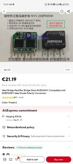
Anyone tried those "ideal" chinese rectifier bridges that are super efficient and additionally smooth out the ripple? I'm considering this to not have to use huge caps but still have minimal ripple.
https://www.aliexpress.com/item/1005002941973887.html
https://www.aliexpress.com/item/1005002941973887.html
Attachments
Can someone remind me how to calculate transistor power dissipation. I have 4 transistors per ch. . Im monitoring total current draw on power supply which is 2.1 amp and have 32 volt rails. Is it just 32x2.1 /4?? So 16.8W per transistor?
Ok follow me here. I get myself so confused on this. Earlier info was off. I'm running F5T on bench with two switching power supplies wired as bipolar so +/- connected together(common) and then + and - to the rails. rails are at 32vdc each. 64vdc rail to rail. I'm monitoring current on + power supply only at 2.1A amp for 4 trannies. So the negative should be 2.1A also. That means total current would be 4.2 correct? Then 64vdc * 4.2A=268W. But now that I'm thinking that each output board only gets either a positive 32 or a neg. 32vdc. So the any transistor will only see 32vdc max correct. Can this also be calculated by emitter resistor voltage drop? I'm monitoring that @ .565vdc across .5ohm. So each trannie is seeing 1.13A. 32 * 1.13 = 36.16W? It just gets confusing.
Current flows form the positive supply to the negative supply through the transistors when no signal is present at input. Thus 2.1A (not 4.2A) is the total current draw.
The simple way to calculate this is the total supply voltage (Vrail x 2) * total current draw, divided by the number of devices. This does not account for tolerances.
Your total is (((32*2)*2.1)/4) = 33.6W per device, as ZM indicates.
The simple way to calculate this is the total supply voltage (Vrail x 2) * total current draw, divided by the number of devices. This does not account for tolerances.
Your total is (((32*2)*2.1)/4) = 33.6W per device, as ZM indicates.
Effective for reducing ripple and noisefloor?yeah
Using them, does it necessitate a different voltage trafo than would be used with simple diode bridge?
Last edited:
Yeah, I was thinking about this option too, but was hesitant to do it, because for some reason most folks seem to be using a trafo. So I thought that may offer some sonic advantages. And for no other reason than having no experience, I somehow think that SMPS is maybe less meaty and lighter in the bass? Are there actually any disadvantages to an SMPS?
I guess they're just charging the capacitors, maybe my fears are completely unfounded and I should just choose the best caps I can get instead of worrying about SMPS being worse in any way.
I guess they're just charging the capacitors, maybe my fears are completely unfounded and I should just choose the best caps I can get instead of worrying about SMPS being worse in any way.
Hello freecrowder,
you can only experience the possibilities (soundwise) of an F5T with really good speakers and a well sounding
source: CD-player, a good streamer, perhaps vinyl,...
No cell phone will show you the real soundquality of this amp (like some members do here).
My F5Ts are sounding very detailed (kind of analytic) and offer also a good bass. But this strongly depends on the speakers.
The speakers are making audible music out of the signal coming out of an amp.
My opinion.
Enjoy your F5T!
Cheers
Dirk 😉
I've been thinking about all of these power supplies and so on and I realized that ultimately if I get a nice oversized SMPS like Meanwell maybe which won't cost me much and design a good filter for it which won't cost very much either, because it doesn't necessitate huge caps.. use air core inductors, ferrite beads etc, maybe use a regulator like Amy Alice at the end of it and then have moderate to large caps 2 to 20 mF at the amp boards themselves with a small ceramic bypass of ~1uF (even though all the filtering was already be enough, I think somehow it's still better to have this kind of isolation that is achieved by caps on the amp board) and either 0.2R resistors or thermistors if it's a bigger cap to limit inrush would isolate virtually all the noise, would reduce the cost significantly, reduce also the weight and the volume. And give me overall much lower noise floor.
I'm thinking about the noise floor so much, because I'm also going to be using it with headphones and also directly to tweeter using active crossover. So probably DC servo and speaker protection are also going to be necessary, but I'll figure that out as I go.
The only drawback that I can think of in terms of serious drawbacks is added complexity and perhaps shorter longevity of smps versus any kind of traditional or non-traditional ("ideal") toroidal PSU. I mean the the toroidal supply with traditional diode bridge is essentially fail proof due to its simplicity.
I also read a lot of reports from users here and audio karma and the the opinions are mixed, but sonically, there isn't a clear winner.
Tl;dr even lower noise, much lower cost (so much less capacitance needed, so many dollars/euros saved) with switchers.
Last edited:
Indeed, good source and speakers are crucial. Usually it's the source that is the bottleneck. Even with the new Chinese stuff in the last few years, which is relatively cheap for the excellent sound quality. I mean you can find very resolving speakers for under 1k, but the DACs are nowhere to be found in terms of being extremely excellent below 1K in my experience, unless DIY I guess and even that costs quite a bit. Streamer isn't needed, DAC is much more important. Vynil might be the cheapest option, but who wants to store a truckload of toxic material in their home and have such limited music choices. Not me. Oh and spend a fortune on the records too.you can only experience the possibilities (soundwise) of an F5T with really good speakers and a well sounding
source: CD-player, a good streamer, perhaps vinyl,...
- Home
- Amplifiers
- Pass Labs
- F5 Turbo Builders Thread