
Hello demonkleaner,
dormant? Could be? Not so many F5T-builds out there at the moment.
I only can say, that my F5T-Monoblocks are still sounding excellent on my electrostats.
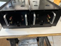
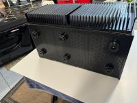
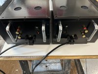
Your project is looking really good to me. Big case - lots of heatsink!
Cheers
Dirk
dormant? Could be? Not so many F5T-builds out there at the moment.
I only can say, that my F5T-Monoblocks are still sounding excellent on my electrostats.
Your project is looking really good to me. Big case - lots of heatsink!
Cheers
Dirk
Attachments

So I was told I could use the 8ma or 11ma jets , cascode amp. Can someone tell me what the 8 vs 11 difference is in this application.
The only difference will be a couple of turns on the bias pots. Functionally and audibly there is no difference and no preference between them.
I’ve got a set of Swans Divas 6.3 that are difficult to drive. I think they’re Hivi’s premium brand? I had an impedance
graph for them somewhere but will need
to look. Don’t think the turbos will break a sweat.👍
graph for them somewhere but will need
to look. Don’t think the turbos will break a sweat.👍
Hello Demonkleaner,
you can ask publicly. Perhaps others can use the infos. If not, then I send you a PM (private message).
Greets
Dirk
you can ask publicly. Perhaps others can use the infos. If not, then I send you a PM (private message).
Greets
Dirk
Thanks!
1. How many sets of OS device’s are you running per channel?
2. What’s your rail voltage and bias setting?
3. Are you using the diodes or did you leave them out?
I’ve read most of the thread but still a bit unsure about some stuff.
Danke!
1. How many sets of OS device’s are you running per channel?
2. What’s your rail voltage and bias setting?
3. Are you using the diodes or did you leave them out?
I’ve read most of the thread but still a bit unsure about some stuff.
Danke!
Hello Demonkleaner,
I will try to answer your questions:
Q1: 4 N-Channel- and 4 P-Channel- Mosfets per Monoblock /channel
Q2: railvoltage is +- 42.7 V DC (I used two 1000W / 2x 30 V AC sec. transformers)
bias-setting per device is 330mV over biasresistor
Q3: I have the MUR-diodes in. This was discussed here in the thread, that it could be better to leave them out.
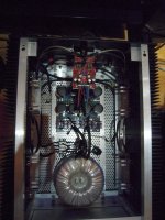
Most important for me was, that I first built the PSU and measured all the voltages.
Then I calculated the resistor - values for the frontend. I have the frontends with a matched octett of Toshiba-JFets and cascoded. Frontend was biased up and adjusted
After each step, I made a dim bulb test. No biasing with dimbulbtester!!!
The final biasing of the outputstages was done extremely careful and slowly - patience is your friend here.
I biased in small steps - no more than 50 mV up and let it cook and checked offset at speakerout and waited till it stabilized. Took more than one or two hours per Monoblock. You put your lid on and will have slightly to readjust. Better to do this after a few days again.
Many want to listen and get in a hurry and impatience. This is the baddest thing you can do.
Cheers
Dirk
I will try to answer your questions:
Q1: 4 N-Channel- and 4 P-Channel- Mosfets per Monoblock /channel
Q2: railvoltage is +- 42.7 V DC (I used two 1000W / 2x 30 V AC sec. transformers)
bias-setting per device is 330mV over biasresistor
Q3: I have the MUR-diodes in. This was discussed here in the thread, that it could be better to leave them out.
Most important for me was, that I first built the PSU and measured all the voltages.
Then I calculated the resistor - values for the frontend. I have the frontends with a matched octett of Toshiba-JFets and cascoded. Frontend was biased up and adjusted
After each step, I made a dim bulb test. No biasing with dimbulbtester!!!
The final biasing of the outputstages was done extremely careful and slowly - patience is your friend here.
I biased in small steps - no more than 50 mV up and let it cook and checked offset at speakerout and waited till it stabilized. Took more than one or two hours per Monoblock. You put your lid on and will have slightly to readjust. Better to do this after a few days again.
Many want to listen and get in a hurry and impatience. This is the baddest thing you can do.
Cheers
Dirk
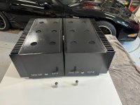
Awesome. I've one mono block ready to leave the fabrication shop (my garage) and go the ham shack (room over my garage).
I have an matched octet of Toshiba v-fets ready to go. Transformers are 25V 800W
PS chokes are monsters but I was determined to use them. German made 2.5MH .1ohm @ 30 A
I really can't see me fabricating any more chassis'. Too much work. My Aleph J went into a Modushop Deluxe 5U and has worked flawlessly.
I have a spare Deluxe 5U and a Deluxe 3U on standby. This makes me appreciate Gianluca and his folks @ Modushop.
They make it easy. Thank you very much for your info. I come from the tube side of things and this is still new to me but I'm learning.
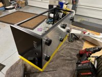
Update with disclaimer: if you are looking for perfection don't click on these photos 😉
All the PS stuff is mounted ready for hook up. The wimpy 12AU7 used for perspective
in an earlier photo has been retired and replaced with a pair of Amperex 6DJ8's as per MZM.
These have 16A entry modules and 12AWG power cords just because. Photos are a bit skewed
due to the bowed plywood they're sitting on.
Attachments
Fugly!
I like them all........
important part of my life philosophy

The wimpy 12AU7.........Amperex 6DJ8's
I like them all........
just because
important part of my life philosophy
Cubicincher, I currently have F5tv3 monoblocks (no diodes) that are running 47v rails. They sound great but I bought 750va 2x 30v secondary transformers with goal to convert them to 40v railed balanced monoblocks. I’m just about ready to embark on making the conversion. Two questions. Would it make sense to build the balanced monoblocks as two stereo amps and bias them in this configuration (my understanding of biasing balanced monoblocks is that it is very time consuming and requires like 6 dmm’s) as easier method? Second, just to confirm: all that is needed to convert a stereo configuration F5t is redoing wiring such that pin 2 xlr goes to input terminal positive input board, pin 1 goes to input terminal negative board, pin 3 xlr goes to ground on both input boards, and input boards are connected via “link” terminals. Finally, output of positive input board goes to red speaker post, and output from negative input board goes to black speaker post. Do I have this right? Any other changes? Thank you!
Hello algg,
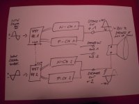
I never tried the balanced confifuration of the F5T like described in the simplified schematic in the article of Nelson Pass.
As I understand it (like you wrote above): out of 1 Stereo F5T amp, you make one channel (balanced) amp.
The two channels on two frontenddriverboards are connected over the link pads (as you wrote above). One channel of the frontend-
boards gets the positive signal, the other channel gets the inverted signal (this is differentially balanced).
But the speakeroutput should be the two speaker - plus from left and right channel. One channel plus gives out the non-inverted signal and the other channel the inverted signal over the (two) positive speakeroutputs.
Often members are confused what is a bridged amp and a real differential working amp
But i can't tell for sure, because i have never tried it wit the F5T!
Greets
Dirk
Dirk, I think that confirms my thinking. I am poorly referring to “negative board” when it really is “inverted signal board” as you said. Your audiostatics are bringing back memories. I owned a pair in the mid 1990’s for about a year. Really liked them but had issues integrating into my system/room so eventually moved on.
My audiostatics got some new foils some years ago and new caps. They are doing a great job from 80Hz up.
Below 80Hz i use a subwoofer.
But I also built different speakers the last few years...
It is always a search for a better - or different - sound.
Cheers
Dirk
Below 80Hz i use a subwoofer.
But I also built different speakers the last few years...
It is always a search for a better - or different - sound.
Cheers
Dirk
I`m also getting my parts in for an F5t V3 build. Rail voltage will be around 45 VDC, for R25, R26 33k and for R27, R28 10k will be used. PSU will be CLC using 44 mF 10 mH 44 mF per rail, so 352 mF in total. Two 800 VA torodials with 33 VAC secundaries. I`m heading for 0,6 - 0,64 A bias per device. Since I use a case with 4 bigger heatsinks for a stereo Build, I should end up with 55 - 56 C according to my calc. If it gets hotter I plan to reduce to 3 pairs of mosfets instead of 4 or I might use fans to get the amp below 55 degrees. the diodes will be used too, as you can see on the pics. Wish me luck! 😃


Last edited:
I'm sitting on a set of DIYAudio Store-matched MOSFET kit for an F5T I'll never build. LMK if anyone's interested.
Question.....I have one mono block up and running. To keep offset @ a few MV I have roughly 50MV difference (across source resistors).
ATM about 310MV across one set of OP's (4 set of devices) and 360MV on the other set. Is this normal? Temp settled at around 50C at
these settings. JFETS are matched quads (cascoded) from Punkydog. 800VA 25V donut. Roughly 32VDC per rail. Driving a test speaker well.
Also no diodes. Big chicken here. Thanks all!
The source resistor voltage difference is probably related to the fact that the N-channel Mosfets and P-channel mosfets have slightly different IDSS, Gfs, etc. characteristics, in spite of being "complementary" devices. As long as the offset voltage is low, and stable, you should be good. I left the Turbo-diodes out of my build also. I also cut the traces between the cascode transistors and the jfets and installed 150 ohm resistors per Nelson Pass's Post #3943.
- Home
- Amplifiers
- Pass Labs
- F5 Turbo Builders Thread