

Just starting to bias a mono F5t,
34-34 volt rail' R25/R26/R27/R28 =10k
P1 & P2 set to zero, dvm across R5 & R6
R5 read's 32.9v, R6 read's 1.2 mv.
Any Ideas ?
34-34 volt rail' R25/R26/R27/R28 =10k
P1 & P2 set to zero, dvm across R5 & R6
R5 read's 32.9v, R6 read's 1.2 mv.
Any Ideas ?
Folks:
The N side of one of my F5T V3 amps released its magic smoke yesterday. I had just walked from the utility room to my basement music room and happened to glance at the V3s when it happened. Out of an abundance of caution, I avoided looking at the other amp. The busted amp has been in service for about 10 years and, to the best of my recollection, this is the first time it has failed. Notably, I did add anti-oscillation caps to the amp's front-end board about 5 years ago.
Two of the FQA16N25C MOSFETs are clearly cooked, but there's nothing else that looks suspect on the N-channel output boards. I have a supply of IRF240PBF quads on hand (as well as quads of IRF9240PBF). I don't know what caused the failure, but I haven't checked the bias or DC offset on the amp in quite some time. The P side didn't smoke but I haven't taken that side apart yet. The insulators are ceramic -- AI203 -- and are intact.
Since I only pretend to know what I'm doing, your advice on my next steps would be appreciated:
1. What should I be testing to verify that nothing other than the MOSFETs need to be replaced?
2. Is there any reason not to replace all 4 FQA16N25C MOSFETs with a matched quad of IRF240PBF?
3. Should I also remove the MUR3020W diodes? Should anything else be removed?
4. Is there a compelling reason to replace the MOSFETs and remove the diodes on the P-channel output boards?
5. Any other suggestions?
Thank you!
Regards,
Scott
Attachments
Hard to say what to do if you don't know why this happened. Those aluminiumoxide insulators are pretty thick, so it wouldn't be that burning through. Maybe a MUR3020 was conducting?
But I think I would go for all new output pairs P and N, just to be sure. They are not that expensive.
But I think I would go for all new output pairs P and N, just to be sure. They are not that expensive.
Walter:
That makes sense. I haven’t read thoroughly on the issue, but isn’t removing the MUR3020 diodes also supposed to reduce oscillation and other failure issues? I’d like to fix and put this amp back into service for the long haul.
Regards,
Scott
That makes sense. I haven’t read thoroughly on the issue, but isn’t removing the MUR3020 diodes also supposed to reduce oscillation and other failure issues? I’d like to fix and put this amp back into service for the long haul.
Regards,
Scott
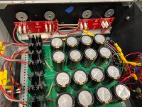
An update on my chassis progress and a question. My sinks are still around 17 lbs. each. The dimensions are about 10"
tall, 22" deep and 2" deep fins. They've been bolted together with a layer of arctic silver between.
Will these support an extra pair of output devices? Transformer is 800W and should yield 24VDC rails.


tall, 22" deep and 2" deep fins. They've been bolted together with a layer of arctic silver between.
Will these support an extra pair of output devices? Transformer is 800W and should yield 24VDC rails.
eyeball, that's good for more than 150W of heat, maybe even close to 200
Folks:
I haven't experienced stability issues using FQA16N25C MOSFETs in my V3s (except for maybe just recently). I have replaced the Fairchilds with IRF240PBF. Will switching to the IRF240PBFs increase the risk of stability problems for me, and is removing the diode something I ought to do now before completing the repair?
Regards,
Scott
I should mention again that the FQA12P20 MOSFETs on the P-channel side show no sign of damage. I'll replace them with IRF9240PBF MOSFETs just in case, but the same question asked above applies: are the IRF9240s more susceptible to stability (or any other) issues than FQA12P20, necessitating my removal of the power diodes on that heatsink as well?
Scott; When I would have to rebuild my F5Tv3 I think I would have let the MUR diodes out. They are a concern that when your bias becomes to high and they start conducting that your amplifier blows up. Nelson put them there to get higher output currents to the speakers when needed. I don't know if you have teriible low impedance speakers or play very load all day? But otherwise I think the MUR diodes are overkill. As far as I know they don't do anything for reducing oscillating of the amp. The same for using IRFP's or FQA mosfets makes no difference.
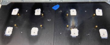
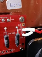
Took another look !
this photo reveals my issue
Aha!! Indeed it does. 🙂
The best fixes are the simple ones. Enjoy the music!!!
are the IRF9240s more susceptible to stability (or any other) issues than FQA12P20, necessitating my removal of the power diodes on that heatsink as well?
I built my v3 balanced monoblocks using the Vishay MOSFET's and MUR3020 diodes, I followed the schematic and BOM to the letter, including adding the capacitors to reduce oscillation. I used the 47 ohm gate resistors which the schematic shows for FQA MOSFETS, had a heck of a time getting bias and especially DC Offset stable. DC Offset would drift +-150mV and bias would increase to the point of smoke/sparks. I ended up removing the diodes, no change except no smoke/sparks, the gate resistors were increased to 470 ohms and then bias and DC Offset were stable for over 2 hours of operation.
Just for grins, I put the Vishay MUR diodes back in the circuit, adjusted bias and DC Offset (still rock stable) and have been running them for the past few months with no issue.
I recently bought enough Harris MOSFET's for both balanced monoblocks, this time I'll remove the diodes, put pins/sockets for all the gate resistors and plug and play gate resistor values until the amp is rock stable. Then I'll put the MUR diodes back in and adjust bias and DC Offset again.
I first want to run the amps for a few months more, I don't want to fry a once in a lifetime chance with the Harris MOSFET's.
- Home
- Amplifiers
- Pass Labs
- F5 Turbo Builders Thread