@joesch1999 I seriously considered using a keyswitch on amps before my kids grew up and moved out, particularly on gear built without protection circuitry.
Its one thing with the kids, but If you're into small full range drivers and
 your spouse or SO happens to be into heavy dub or is otherwise extremely ~distortion tolerant ~, protection circuitry is probably easier than the inevitable discussion about trust.
Its one thing with the kids, but If you're into small full range drivers and

protective cage is solution
put kids in cage

put kids in cage
We are divorced now 🤣 just want to get my f5 turbo back in its beautiful glory. I miss the hair standing up on the back of my neck while it plays. It still works it just sounds like a kenwood amp 😬 I had a chance to test the the irfp240 and the n channel none are shorted. I’m really leaning towards the j fets being bad as the speaker output is only +.50 volt@joesch1999 I seriously considered using a keyswitch on amps before my kids grew up and moved out, particularly on gear built without protection circuitry.
Its one thing with the kids, but If you're into small full range drivers andView attachment 1328050 your spouse or SO happens to be into heavy dub or is otherwise extremely ~distortion tolerant ~, protection circuitry is probably easier than the inevitable discussion about trust.
Last edited:
Have you checked for bias voltage across your upper and lower pots? I'd guess your jfets are likely gone. Btw, if you have a thermal camera, you can tell at a glance if your fets are conducting.
Yes I found a broken power wire to the n channel hooked it up blew a 240. I have a matched set to throw in, I’ll do that use my variac , turn down the bias on both channels as I do not remember the directions of the pots. I know one goes clockwise the other counter clockwise. This is on the left channel.
F5T 3 channel mono block heat test
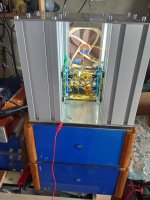
I'm heat testing this 3 channel F5T mono block, comprising four vertical pillars of extruded aluminium box section heat sinks (metal thickness 2mm).
Three Pillars have an F5T pcb mounted vertically, each with a pair of Vishay/Siliconix IRFP240/IRFP9240, one device higher on the sink, and the other device about 8cm below it. The fourth rear right pillar is not used for the moment.
A single 14cm Noctua ULN fan sucks air from the back and blows out to the front, across front pcb's for channel 1 and 2 (Upper mid and Lower mid respectively). Channel 3 (Tweeter) is on the rear left sink, around the corner from the direct air flow.
Channel 1 (for driving 4 ohm load):
0.90A bias @ 55V rail to rail = 50W total, or 25W per device. Higher N type @ 106 C, Lower P type @ 103 C measured on devices metal tab. The plastic case is about 20 degrees C below this (this is what the thermistor sees). Sink temp @ mid point between devices is 54 C.
Projected Junction temp would be 0.83*25=21 C higher than metal tab temp i.e between 127 C & 124 C, which is below absolute max junction temp of 150 C.
Ambient temperature is 25 C, and measurements were made with thermocouple probe & meter.
Whilst the Junction temp is still below the absolute maximum rating, I'm wondering if anyone has experience or comments about projected reliability at these temperatures?
(The other two channels are operated at lower bias of 0.76A and have metal tab case temperature of about 88 C for channel 2 and 95 C for channel 3 due to reduced air flow around the corner of that sink)
Attachments
Temperatures are little higher than recommended but should be fine in the short term.
The big issue is that ~1A bias is significantly lower than what is recommended for any configuration of this amplifier. Not going to broach the 700mA version here.
I don't know what the build objectives are, but you should be looking at something above 1.4A for a two-pair config, ideally 1.6A or more for proper sonic performance. Output transconductance is too low to meet the base spec of this amplifier. I would really recommend sticking close to the datasheet recommendation of 32V rails, maybe 35. 55 is just unworkable for a two pair configuration with such a simple input stage.
Sangram, thanks for the comments.
The purpose of this multi-channel effort is to drive a 4 way open baffle dipole speaker like the Linkwitz LX521.4.
The lower channel #4 sub woofer (4 ohm) is handled by a separate 150W class B mono block seen at the base of the 'tower'.
The F5T are only for the upper 3 channels which are reasonably efficient and probably only require a few watts per driver to fill the room with the dipole sound field.
I should just clarify though that with 55V rail to rail, I meant +-27.5V rails.
I might like a bit more bias on Channel 1 though, because it drives a 4 ohm driver which is also the least efficient. However, on these sinks I wouldn't really like to increase the bias and temps any more than they already are, so in that case I would opt to have a parallel pair of output devices only for this channel on the fourth currently unused sink, and maybe run each at say 0.7A giving a total of 1.4A while also bringing down the junction temps a bit.
They're running just fine and stable right now, but it's the long term reliability that I'm thinking of.
Last edited:
My mistake, then.
The temperatures are quite high for that level of operating bias. I would not typically be comfortable above 70C on the tab (I measure at the drain lead). In the ten or so builds I have running in the wild, there's not been a single thermal failure, and we live in a hellishly hot country.
Your call though. I would think of adding more airflow if you wish to stick to this level of bias. If you only need a few watts, you may consider dropping the voltage down to a lower level and retain the target bias current.
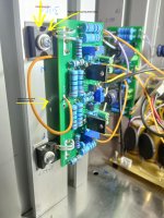
I finally finished one of the Balanced F5t mono blocks (left channel), it has a separate chassis for the power supply. The final adjustment was P3 on the two input boards, I've been listening to the amps since April 2024 so they would be broken in.
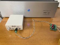
Using my Akitika 1kHZ 2ppm sine wave generator, cubicincher warned me the outputs of the Akitika were different voltages, he was correct. The only solution I found that would output a balanced input to the amp, was to feed the Akitika into Rod Elliott's Project 176 Fully Differential Amplifier.
It worked like a champ! Equal voltages at IN+ and IN- measured to ground. I adjusted the Akitika for 2.83 VAC into an 8 ohm load, I made the adjustments of P3+ and P3- so that H2 was 0.046% and H3 at 0.012%.
Attachments

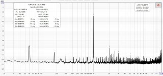
Here is the Right channel, notice the 60Hz on the left (20dB above noise floor) and right (34dB above the noise floor). I used different outlets on different mains circuits in my workroom.
I found the P3 adjustment made a significant change to H2, very little change to H3 with the Balanced version of the F5t. 48VDC rails, biased to 350mV across the test points, DC offset less than 7mV at the speaker terminals.
I built these for my B&W 804D speakers, they appreciate high wattage amps.
I found the P3 adjustment made a significant change to H2, very little change to H3 with the Balanced version of the F5t. 48VDC rails, biased to 350mV across the test points, DC offset less than 7mV at the speaker terminals.
I built these for my B&W 804D speakers, they appreciate high wattage amps.
Attachments
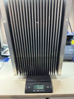
I have a pair of these. Roughly 10”x17” at close to 17lbs each. Plan is to cut them in half and join the halves a la Modushop style.
I’d like to run an extra set output devices and hope this will handle them. Trying to avoid any sort of forced air solutions. Thoughts or observations welcome. Wish me luck!
I’d like to run an extra set output devices and hope this will handle them. Trying to avoid any sort of forced air solutions. Thoughts or observations welcome. Wish me luck!
Attachments
Demonkleaner:
That's going to make one enormous chassis. What do you intend to install in it? Maybe mono blocks instead?
Regards (and great luck!),
Scott
That's going to make one enormous chassis. What do you intend to install in it? Maybe mono blocks instead?
Regards (and great luck!),
Scott
I agree. My wife suggested I take up needlepoint. Would be easier on my back.
Gonna weigh my options (pun intended).
Monoblocks are probably the best way to go
But building the housing would be more
difficult than having two sinks to build around. For me anyway. Actually got them bandsawed in half and the protruding sides
cut off. Next step will be the bead blaster while protecting the component side of course. Already have most of the inside bits from the store. Your comments and encouragement are very much appreciated!
Okay....after working on just the heatsinks I realized SRMcGee is spot on.
Jamming this into one enclosure is the definition of insanity. Once the sinks
are complete I'll get an accurate size measurement and decide about the quantity
of output devices. Already have 2 Antek 800W 24V donuts and 16 27,000uf
50V Panasonic caps to go on the store PS boards. One question, is there a good link
to Nelson's original article on the F5T V3 ? Seems all the links I've found are dead.
Thanks!
One of many more questions: What is the most practical way to achieve a balanced in
on this amp? I noticed the jumper used in the input board (build guide) for SE operation. Is it as
easy as leaving the jumper out for balanced input? I've seen everything from using transformers, dedicated revamped pcbs and the fully input differential boards. Wouldn't pursue this but my DAC and pre are balanced. The balanced Aleph J blew me away and I'd like to keep the "magic".
Thanks for your patience.
- Home
- Amplifiers
- Pass Labs
- F5 Turbo Builders Thread