Ok got it. Thanks AudioSan, this will be exciting. 🙂 (hope I don't get anything into flames)
Last edited:
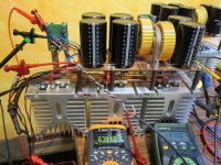
Finally testing my F5T-Channels 😀, everything looks good so far 🙂.
Setup: 33V rails, 3x IRFP9140 + 3x IRFP240, CLC with 141mF/1mH; 0,5 Ohms Resistors, 9,8mA Jfets, Bias 2 Amps.
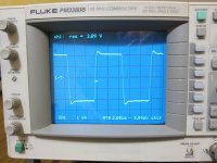
When fed with a square wave, the output voltage does overshoot a bit, at least more than depicted in the F5T article. Could this be related to the use of IRF-devices instead of Fairchild ? I couldn´t get FQAs anywhere.
The overshoot could be trimmed a bit by changing P3, but this also changed the straightness of the rest of the positive/negative output signal.
If anyone has an idea on this, i would be grateful to hear.
Can´t wait to listen to the F5T - have to do the enclosure still - especially as to how it compares to my A75. 😀
Greetings
norb
Setup: 33V rails, 3x IRFP9140 + 3x IRFP240, CLC with 141mF/1mH; 0,5 Ohms Resistors, 9,8mA Jfets, Bias 2 Amps.
When fed with a square wave, the output voltage does overshoot a bit, at least more than depicted in the F5T article. Could this be related to the use of IRF-devices instead of Fairchild ? I couldn´t get FQAs anywhere.
The overshoot could be trimmed a bit by changing P3, but this also changed the straightness of the rest of the positive/negative output signal.
If anyone has an idea on this, i would be grateful to hear.
Can´t wait to listen to the F5T - have to do the enclosure still - especially as to how it compares to my A75. 😀
Greetings
norb
Attachments
For the standard F5 Turbo V1 (no diodes or whatsoever, just higher rail voltage + 2 output pairs), is it ok to go for 0,5V voltage drop around the source resistors (as in standard F5T papers, 2 1R 3W Resistors, so 0,5R total) to go for a total of 2A bias per channel? Or should I exchange the source resistors to, lets say 0,68R and thus decrease the voltage drop?
Regards,
Fabian
Regards,
Fabian
Finally testing my F5T-Channels 😀, everything looks good so far 🙂.
Setup: 33V rails, 3x IRFP9140 + 3x IRFP240, CLC with 141mF/1mH; 0,5 Ohms Resistors, 9,8mA Jfets, Bias 2 Amps.
When fed with a square wave, the output voltage does overshoot a bit, at least more than depicted in the F5T article. Could this be related to the use of IRF-devices instead of Fairchild ? I couldn´t get FQAs anywhere.
The overshoot could be trimmed a bit by changing P3, but this also changed the straightness of the rest of the positive/negative output signal.
If anyone has an idea on this, i would be grateful to hear.
Can´t wait to listen to the F5T - have to do the enclosure still - especially as to how it compares to my A75. 😀
Greetings
norb
Putting a 1000pF to 2000pF cap across the feedback resistors will fix the overshoot.
You can also change the value of the input resistor.
Hi 2picoDumbs,
thanks for your proposals.
During testing one of the output IRFs blew, I had the NTCs connected to the output instead of supply voltages (damn !!). Hopefully it will be OK after fixing this, otherwise i will try your ideas.
thanks for your proposals.
During testing one of the output IRFs blew, I had the NTCs connected to the output instead of supply voltages (damn !!). Hopefully it will be OK after fixing this, otherwise i will try your ideas.
For the standard F5 Turbo V1 (no diodes or whatsoever, just higher rail voltage + 2 output pairs), is it ok to go for 0,5V voltage drop around the source resistors (as in standard F5T papers, 2 1R 3W Resistors, so 0,5R total) to go for a total of 2A bias per channel? Or should I exchange the source resistors to, lets say 0,68R and thus decrease the voltage drop?
Regards,
Fabian
yes. 1A pr device is no problem with +/-32V rails. thats 32W dissipation pr fet.
Hi there.
Any ideas on how to implement a "leaving class A" indicator with a LED for example, for the F5 turbo?
As far as I know, the vumeter on the Pass Labs amplifiers are not really vumeters but act as indicators (when the niddle moves) that the amplifier is leaving class A operation and entering into class B.
Is there a relatively easy way to implement something like this but with a LED acting as this indicator? i.e. that the led starts to light when leaving class A operation?

Any ideas on how to implement a "leaving class A" indicator with a LED
You will probably only want one indicator.
Take a look at the original F5 circuit, delete R21 & R22, disconnect the collectors of Q5 & Q6 and add an LED and resistor in series with each, connect the other end of the LED/resistor string to 0V, adjust the attenuator (R17 R19 & R18 R20) to suit your bias level ie. Turbo values 1A & 0.5R, leave class A at 2A (x 0.5R = 1V), with R17 & R18 = 1K, R19 & R20 = 2K that should put you somewhere in the ball park.
Last edited:
You will probably only want one indicator.
Take a look at the original F5 circuit, delete R21 & R22, disconnect the collectors of Q5 & Q6 and add an LED and resistor in series with each, connect the other end of the LED/resistor string to 0V, adjust the attenuator (R17 R19 & R18 R20) to suit your bias level ie. Turbo values 1A & 0.5R, leave class A at 2A (x 0.5R = 1V), with R17 & R18 = 1K, R19 & R20 = 2K that should put you somewhere in the ball park.
great! Would this impact sound quality ?
great! Would this impact sound quality ?
Couldn't say either way for definite without trying it.
advice required
hello
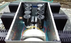
I am at an early a f5t build, trying to see how the components will arrange internally. the heat sinks in use are quite deep, so width is a little limited (they were a donation so felt compelled to use them) however gained a bit on usual case height.
The photos depict the space available, also I have blue tacked some jar lids! to indicate were inductors may be placed .
I have a couple of concerns.
1, the co-location of the output devices to the transformers, currently a 30mm gap.
2, is this an acceptable location for the inductors.
Would really appreciate some opinions


regards
hello
I am at an early a f5t build, trying to see how the components will arrange internally. the heat sinks in use are quite deep, so width is a little limited (they were a donation so felt compelled to use them) however gained a bit on usual case height.
The photos depict the space available, also I have blue tacked some jar lids! to indicate were inductors may be placed .
I have a couple of concerns.
1, the co-location of the output devices to the transformers, currently a 30mm gap.
2, is this an acceptable location for the inductors.
Would really appreciate some opinions
regards
From what I can see, it looks like you will have a difficult time reaching the pots to adjust bias and offset. The amp will need to be at operating temp and running: a slip of the screwdriver could prove very exciting!
Hal
Hal
You will probably only want one indicator.
Take a look at the original F5 circuit, delete R21 & R22, disconnect the collectors of Q5 & Q6 and add an LED and resistor in series with each, connect the other end of the LED/resistor string to 0V, adjust the attenuator (R17 R19 & R18 R20) to suit your bias level ie. Turbo values 1A & 0.5R, leave class A at 2A (x 0.5R = 1V), with R17 & R18 = 1K, R19 & R20 = 2K that should put you somewhere in the ball park.
Great. Thank you. I may try this once I finish the amplifier.
What are the actual dimensions of the heatsinks? They look small for a F5T.
The heat sinks are not depicted in the photos, but here now. The alloy plate= 222mmx400mmx10.9mm, the fins are 222mmx95mmx70mm, each assy =9kgs, I milled a couple of thou off the mating face of the fin's, to get a better contact.
Attachments
By the way, does anybody has a recommendation of fuse value if my power transformer is 1KVA (120Vac mains)? I plan to use a soft-start circuit.
Mr. Pass recommended a 4A slow fuse in the F5T article, but is this the same for different transformer specs?
Thanks!
Mr. Pass recommended a 4A slow fuse in the F5T article, but is this the same for different transformer specs?
Thanks!
From what I can see, it looks like you will have a difficult time reaching the pots to adjust bias and offset. The amp will need to be at operating temp and running: a slip of the screwdriver could prove very exciting!
Hal
Thanks for your concerns.
Bourns manufacture a pot with side entry, this will allow vertical access to P1 & P2. P3 legs can extended and turned through 90deg for same access, not pretty but a fix. The bourns pot adjusting tool is plastic and the tool for the job, but will still take heed of your advice when dealing with live power supplies.
By the way, does anybody has a recommendation of fuse value if my power transformer is 1KVA (120Vac mains)? I plan to use a soft-start circuit.
Mr. Pass recommended a 4A slow fuse in the F5T article, but is this the same for different transformer specs?
Thanks!
1KVA/120V=8.3
say that 8A slow blow (T) will do the job
Yes and by my experiments with 240Vac you should find that by restricting the worst case starting current to ~16A that the T8A fuse will not blow. 115Vac/16Aac = 7.2Aac.1KVA/120V=8.3
say that 8A slow blow (T) will do the job
A resistor of 6ohms to 8ohms should limit the current correctly.
- Home
- Amplifiers
- Pass Labs
- F5 Turbo Builders Thread