My F5 supply is oscillating with 2,7 mh ferritcoils. Without there is no problem.
Could you provide some more info on set up and caps / capacity used?
Also, depending on the type of inductor, I'd guess that the ferrite core will saturate at the idle current of the amp, thus decreasing the inductance considerably. Is it possible the change of inductance (during turn on) causes oscillation?
I was slowly turning it on with a vario. There where only 1 vdc on the 720.000 uf. My conclusion is that I can not use that kind of coil and I ordered 4 x Hammond 156 b. So I will try them when they arrive.
Different output in the two channels
During the three last years I have built several F5, both V2 and V3. Not for my own use, but for others. Now I want to help a friend of mine with his F5V2 having the following problems (I have never run into the same problems with the F5 I have built):
When output is measured, there are a difference in output of 3dB between the two channels. To set bias 100 ohms are used in all four position (R5/6 andR7/8). With my DATS V2 Audio Test System it is possible to measure very exactly with this resistors mounted on the PCB. Results was very close to 11 ohms on both sides on one channel (!?), but very close to 30 ohms(correct?) on the other. Why the results differ so much is very surprising since the same resistors and the same value are used in this position.
My friends wishes is to go for the lowest gain
Will the right cure solving the 3db difference be to mount one resistor on both sides of R5/6 and R7/8 in parallel? A resistor with a value of 18 ohm on both sides, which measured 30 ohm, will bring the total resistors value down to 11 ohm. Is this the “right way” to fix this problem?
If yes, will a ½ W resistor be safe enough for paralleling or must it be 3W like all the others?
Or is this problem to be search for another place on F5V2?
Eivind Stillingen
Eivind,
What is the brand of resistor we are dealing with? Do they measure correctly out of circuit?
From memory, the approximate value you should get when measuring across is closer to 30 ohms than 11. However resistors should always be measured out of circuit. Disconnecting one lead is usually enough.
What is the brand of resistor we are dealing with? Do they measure correctly out of circuit?
From memory, the approximate value you should get when measuring across is closer to 30 ohms than 11. However resistors should always be measured out of circuit. Disconnecting one lead is usually enough.
the NFB string of 50r plus 10r sees the whole output signal.
If the output signal is 20Vpk then the current through the NFB string will be 20Vpk/{50+10} = 0.33333Apk
Now you can calculate voltages and dissipations.
the 10r has 3.3333Vpk across it when the output is at 20Vpk and has an instantaneous peak dissipation of 1.111Wpk = 0.55555W
The 50r has 16.6666667Vpk and 5.5555Wpk = 2.77777778W
since we now know what voltage is across the 50r we can assume the added parallel resistor will see the same imposed voltage.
P in Watts = Vpk²*R/2
That's what you need to solve your dissipation prediction.
But first you need to find out why one channel is giving the wrong output and/or gain.
Check the input, check the output, check the gain.
Last edited:
I am wondering if it makes sense to tune the resistors next to the NTCs to the actual Vgs of the output devices. In the F5 schematic given in the art_F5_turbo.pdf these are R21 and R22.
The Vgs for all the MOSFETs I am going to try range from 2.2V to 5.6V. How would I go about to adjust R21/22 to Vgs other than the 3.6V presumed in the article?
The Vgs for all the MOSFETs I am going to try range from 2.2V to 5.6V. How would I go about to adjust R21/22 to Vgs other than the 3.6V presumed in the article?
Not enough bias adjustment
6L6,
Thanks for your post 4040. Brought up a repaired channel and it ran out of bias adjustment. Only went to .240 volts. It was due to 8mA idea of jfets. Changed R5 and 6 to 2.2k from 1k. Now adjusting fine. 🙂
Thank you,
Vince
6L6,
Thanks for your post 4040. Brought up a repaired channel and it ran out of bias adjustment. Only went to .240 volts. It was due to 8mA idea of jfets. Changed R5 and 6 to 2.2k from 1k. Now adjusting fine. 🙂
Thank you,
Vince
The problem I wrote about in post 4225. Bad connection(cold soldering) on R7.
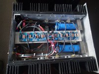
Now to another question. Take a look at the photo. I have built two V3 Turbo where the FETs are connected with separate wires due to use of two heatsinks, one on each side of the PCB (from Jims Audio). Will it bee any risk to run into trouble with this way of mounting. If there is, what will be the "cure"?
Now to another question. Take a look at the photo. I have built two V3 Turbo where the FETs are connected with separate wires due to use of two heatsinks, one on each side of the PCB (from Jims Audio). Will it bee any risk to run into trouble with this way of mounting. If there is, what will be the "cure"?
Attachments
Ideally your leads would be very short. As it is already built see how it works and report back.
I have gotten away with pushing conventional wisdom...and sometimes not. You won't ruin anything with what you have done.
If you get noise or poor quality sound you can try creating a new box with the heat sinks closer to the board and the PSU underneath. this will allow for much shorter leads 😛
Cheers!
Thanks to a note from VDI_NENNA,
I had an issue with my recently built F5T, in which I could not get the bias above 40mv across the source resistors.
He pointed me in the direction of posts #4440, and #4429, with the suggestion to change r5 and r6 from 1k, to 2.2k (of which I had a bag full as they are used for r11, r12).
Last night I swapped them out, and now the amplifier is a breeze to bias. I set the bias to 250mv to test, took it up to 500mv to confirm that I had adequate range, then back to 250mv for a heat soak. Still had very fine control of the adjustment.
After an hour with both channels bias'ed to 250mv, the heat sinks were noticeably warm, the MosFet mounting screw were hot, and the DC offset 0-4mv, so I connected some speakers .... and .... Is it on ? is it on ?? I ask my self 🙂
Starless and Bible Black.
Tonight time to move it into the living room for a test with preamp input ....
Last edited:
Starless and Bible Black.
A most excellent album to christen your amplifier with, hope you Discipline yourself to play the other albums 😀
First Play ?
Well I haven't listened to DB all week, as I just couldn't bear it.
But ..... Might have to give Ziggy a spin tonight to Christen the amp...
It does say on the back of that album Jacket.
"To Be Played At Maximum Volume"
Anyway, as DB was a friend of Mr Tripp, maybe some King Crimson in the number 2 slot.
Most likely your over 50 as well Itsmee ?
🙂
Most likely your over 50 as well Itsmee
Only a little, does it show LOL, if your playing late at night, maybe some Islands or Larks Tongue, if its not so late and you want to test the bottom end, try this - Dub Dynasty Thundering Mantis, track 11 Thundering Mantis Pt II
https://www.youtube.com/watch?v=0y04PLAuftI
or try Solar Fields Mirrors Edge Introduction
https://www.youtube.com/watch?v=iqFLp0jI8lY
You'll love it, it's a way of life . . .
Frank Zappa - Joes Garage
Last edited:
Apropos of cascoding the F5 Turbo front end:
Since the original, playing with this sort of circuit and with different devices and
such, I decided that there is a stability advantage to having some resistance
off the Drains of the input devices when cascoding. This means 100 to 200
ohms (or so) between the Drains and the Emitters of the cascode transistors.
I have seen several examples of cascoded F5's tend toward oscillation, often
fixed by a lag resistor (Drain to Gate) on the outputs, but traceable to the
low impedance seen by the input device Drains (the Cascode).
Particularly with Lateral output Mosfets.
So if you run into this issue, you can try this. Or try it anyway...
😎
How about a 15V zener above the jfet drain instead of a cascode transistor to reduce the voltage and power dissipation seen by the jfet? This would preserve the load impedance seen by the jfet thus also preserving the Miller integration time constant due to the jfet Cgd and the jfet input and output impedances.
How about a 15V zener above the jfet drain instead of a cascode transistor to reduce the voltage and power dissipation seen by the jfet? This would preserve the load impedance seen by the jfet thus also preserving the Miller integration time constant due to the jfet Cgd and the jfet input and output impedances.
Just wondering that if one incorporates Papa's suggestion of adding the resistor can one then safely eliminate using C3 and C4 which is marked optional but many feel should be included to prevent oscillation?
Thanks. Nash
Shielding inductor in CLC?
I intend to build a F5T with a CLC power supply (using air coils to avoid core saturation).
How much sense does it make to shield the inductors to reduce the magnetic stray field, and to avoid it from interacting with the rest of the electronics?
How would you construct the shielding (material, etc.)?
- Home
- Amplifiers
- Pass Labs
- F5 Turbo Builders Thread