Green wire connects amplifier boards grounds together
That is creating a loop, I would cut that one out.
I wonder if any member has connected two independent secondary with one bridge.
Bkink, I just noticed that the burning amp 1 psu is wired that way, as 6L6 said it is common.
I think it's probably a better idea to use dual rectifier bridges with a dual secondary transformer. However, the single bridge does work, and has been used in many successful commercial and DIY projects.
I think Nelson usedit in the F5T article mainly to utilize the MUR3020 diodes.
This is a time when there is more than one correct answer to the question. Remember that we need +32v/GND/-32v clean, quiet, and of sufficient current to keep the amp happy. There are lots of ways to do that. 🙂
I think Nelson usedit in the F5T article mainly to utilize the MUR3020 diodes.
This is a time when there is more than one correct answer to the question. Remember that we need +32v/GND/-32v clean, quiet, and of sufficient current to keep the amp happy. There are lots of ways to do that. 🙂
Question - Has anybody had a successful build of a V2 or V3 using the seperate toecutter Front-end board and output boards?
I know there are a few all-in-one boards out there, I'm interested in the 3-peice (or more) boards.
I know there are a few all-in-one boards out there, I'm interested in the 3-peice (or more) boards.
I have a single bridge with two transformers tied together I am trying different things to learn. I started with single transformer single bridge.Now that I received more diodes I'll build one more bridge. One for each transformer Later separate capasitor banks I still have a small buzz only heard on quiet passages of music however I am spoiled as my F5 is dead quiet. I have had noisy risitors in the past as you can see from pictures I am using rather inexpensive ones.I will also try removing transformers from the chassis and running long wires to ps probaly next week as it's a beautiful day I'm going to take a hike.I think it's probably a better idea to use dual rectifier bridges with a dual secondary transformer. However, the single bridge does work, and has been used in many successful commercial and DIY projects.
I think Nelson usedit in the F5T article mainly to utilize the MUR3020 diodes.
This is a time when there is more than one correct answer to the question. Remember that we need +32v/GND/-32v clean, quiet, and of sufficient current to keep the amp happy. There are lots of ways to do that. 🙂
My amp section is wired and biased;just the power supply box to make when the aluminium finally arrives.
I really must get my eyes tested. 😉
I really must get my eyes tested. 😉
hi looking good!
Back off about 6 " and then crop the pic it will be in focus then,not so fuzzie,I like the add on heatsink Idea!Good work!
NS
Back off about 6 " and then crop the pic it will be in focus then,not so fuzzie,I like the add on heatsink Idea!Good work!
NS
Question - Has anybody had a successful build of a V2 or V3 using the seperate toecutter Front-end board and output boards?
I know there are a few all-in-one boards out there, I'm interested in the 3-peice (or more) boards.
hello. i have a successful power up of this boards. well. i have only fired up the front ends yet. with cascoding.
Question - Has anybody had a successful build of a V2 or V3 using the seperate toecutter Front-end board and output boards?
I know there are a few all-in-one boards out there, I'm interested in the 3-peice (or more) boards.
6L6
Would you like me to send you a set to play with?
Question - Has anybody had a successful build of a V2 or V3 using the seperate toecutter Front-end board and output boards?
I know there are a few all-in-one boards out there, I'm interested in the 3-peice (or more) boards.
They will make changing out the cooked mosfets easier! Have you figured out what keeps zapping them? I'm wondering if I should pay for some extra sets...
Russellc
UKToecutter - Would you please PM me with your email? I have a few questions that you can best answer. 🙂 Thank you!
Russellc - No, I haven't yet. 3 channels worth so far... 🙁 It's not a problem, it's a challenge! 🙂
Russellc - No, I haven't yet. 3 channels worth so far... 🙁 It's not a problem, it's a challenge! 🙂
Blink, your transformer is a good choice, 2x24 v coils is perfect, I wish I had one. You dont need a center tap, although with dual secs, you can always make one. If you want split rails, you should do as NP has drawn in the FirstWatt and Zen articles. Run two rectifiers instead of one and ground the middle of the psu, that will stop iduction on your ground wire.
The confusion was because I used a single bridge, as in the original, and gave me 0 zero volts because I measured without the GND.
Redid everything again and found that the wires are in 48V AC.
All mounted only with a bridge, 4x MUR3020W, and was connected to 0.29V for 1 hour.
Very good sound, but there was still a slight hum, so I thought, I'll switch to two bridges, and used the KBPC3504W. I got the feeling of having reduced the level of tinnitus and it seemed more fluid sound, but perhaps it is the placebo effect!
It's a matter of doing more experiments, although the MUR are of 35nS and faster than KBC, have to find bridges faster than KBC ...
when using single bridge was there hum with grounded inputs?The confusion was because I used a single bridge, as in the original, and gave me 0 zero volts because I measured without the GND.
Redid everything again and found that the wires are in 48V AC.
All mounted only with a bridge, 4x MUR3020W, and was connected to 0.29V for 1 hour.
Very good sound, but there was still a slight hum, so I thought, I'll switch to two bridges, and used the KBPC3504W. I got the feeling of having reduced the level of tinnitus and it seemed more fluid sound, but perhaps it is the placebo effect!
It's a matter of doing more experiments, although the MUR are of 35nS and faster than KBC, have to find bridges faster than KBC ...
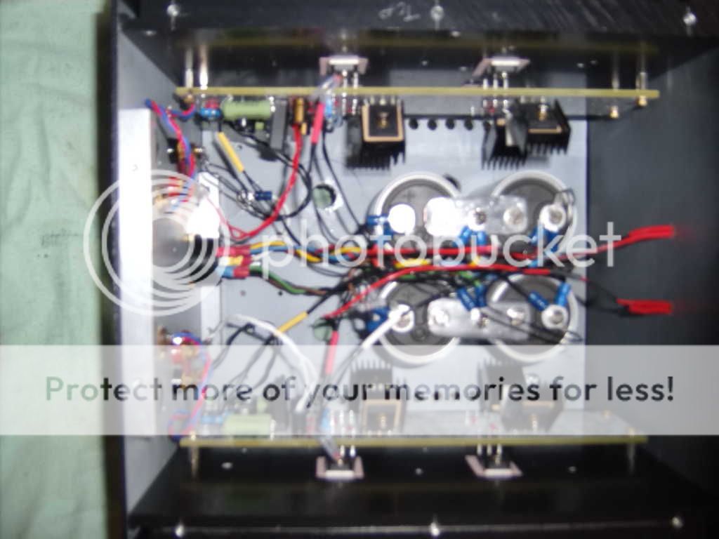
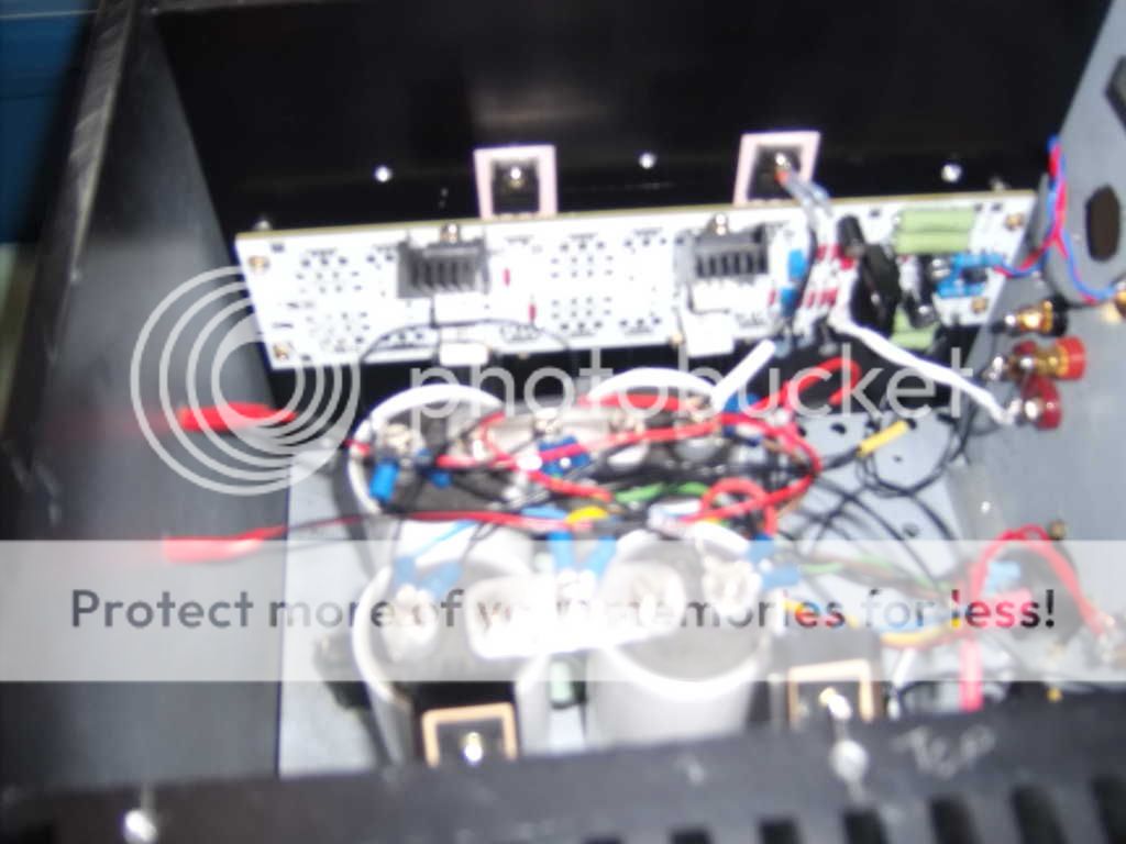
Thanks for the tip NS heres a couple of less fuzzy pics.
Aluminium arrives tomorrow so I should,fingers crossed, have a working amp in a few days time.Heatsinks on the diodes is a copy of Buzzforbs V3.
Aluminium arrives tomorrow so I should,fingers crossed, have a working amp in a few days time.Heatsinks on the diodes is a copy of Buzzforbs V3.
An externally hosted image should be here but it was not working when we last tested it.
An externally hosted image should be here but it was not working when we last tested it.
Last edited:
when using single bridge was there hum with grounded inputs?
It's always when I connect the imputs I hear a small hum.
With a bridge or two I hear, but I think with the two seem to give less buzz. I will test more ...
If you disconnect the RCA cables is okay, like a stone ...
I removed the 8 sinks in MUR3020W (pcb channel), they are cold, seemed antennas.
Last edited:
It's always when I connect the imputs I hear a small hum.
With a bridge or two I hear, but I think with the two seem to give less buzz. I will test more ...
If you disconnect the RCA cables is okay, like a stone ...
I removed the 8 sinks in MUR3020W (pcb channel), they are cold, seemed antennas.
So do I. There is hum when I connect input signal. I cannot fix it.
- Home
- Amplifiers
- Pass Labs
- F5 Turbo Builders Thread