Thanks for the tip NS heres a couple of less fuzzy pics.
[/IMG]
😀😀😀 OK fair enough undervare is ok maybe just one day off and is that 32DD maybe better picture is needed.
But Red soks no please 😀😀😀
(only joking neh!)
Hat off to you Sir!
own you a pint just for sound sense of humor.
Sorry is in the Pub (no not realy) could not resist.
own you a pint just for sound sense of humor.
Sorry is in the Pub (no not realy) could not resist.
When I turn my amplifier off amplifier keeps playing for a few seconds but hum stops immediately so I thought to much ripple in ps so I wired in a few chokes I had for a speaker project 2.7mh plus one more bank of caps this dropped my voltage down to 29v at output to amp boards but also added more filtering for dc I also removed ground bar from one side of first part of ps as this was creating a loop.So do I. There is hum when I connect input signal. I cannot fix it.
Hum is very low now but still there. I bought these caps at surplus store and I don't know there ripple rating. Here's a picture. I also wired in one more MU3020 bridge so now one transformer -bridge is powering positive ps and the other the negative.The bias seems more stable now. This may also be from the amp settling in as it's new.
Attachments
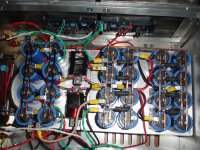
wow... capacitors galore. nice job soldering those fat copper wires. This could be a case study of how to make a power supply.
or - how to not
positive , gnd , negative takeout points to amp pcbs - all of them need to be on two last caps in filter
expand that pic , open it in Paint or other graph proggie , mark and write down function of each wire and post it here
then I'll tell what and where to re-locate
positive , gnd , negative takeout points to amp pcbs - all of them need to be on two last caps in filter
expand that pic , open it in Paint or other graph proggie , mark and write down function of each wire and post it here
then I'll tell what and where to re-locate
I would tend to agree with Zen on this one... this looks like a mess for us who didn't build it.
Not claiming that what I do is better.... 🙂
Not claiming that what I do is better.... 🙂
Thanks Zen Mod! I'm not able to manipulate pictures but I can mark wires and post new pictures with marked wires.would that be acceptable?
1 = + side from first bridgejust put some tapes on wires with numbers on them
2 = - side from first bridge
3 = - side from second bridge
4 = + side from second bridge
5 = + input to first choke
6 = - input to second choke
7 = + output from fist choke to + caps
8 = - output from second choke to - caps
9 = amp board ground
10 = amp board ground
11 = + output to amp board one
12 = - output to amp board one
13 = + output to amp board two
14 = - output to amp board two
15 = ground to ground bridge
16 = cap ground connector
The other wires are speaker outs and rca inputs
If this is not clear let me know and I'll elaborate.
Attachments
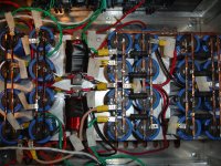
this is a mess. i'm getting dizzy trying to follow the wireing🙂 start in one end with bridges. and finnish it at the other end to the amp Boards. and get the inductors in between.
Good news ... I have what is essentially a V1 up and running. Getting the source diodes in the circuit is the next step. (which will make it into a V2)
I try not to listen to ZM at all. I don't know what's wrong with you people. Just sitting here listening to wonderful live sting concert given to me by a friend. Thank you Mr. KGB
Nice to hear 6L6🙂 what was wrong With it?
As far as I can tell, because it blew up twice before I ever had a scope on it, oscillation was eating up the gatestoppers and then the outputs failed. Don't take it to court, but the circumstantial evidence is pretty good...
nrg2009 said:Very good 6L6. All future V2 builders (including myself) await your verdict on the boards.
As soon as I get it happy with the source diodes in the circuit, and buzzforb has no issues with his, then I'll be happy.
My guess is that the small (1000pf) compensation cap from gate to output, which is mentioned in the V3 instructions, should be considered standard. Luckily there is room for it on the output boards. 🙂 🙂 🙂
- Home
- Amplifiers
- Pass Labs
- F5 Turbo Builders Thread