aha. your high rail voltage meens no current draw. messure voltage between P-ch source resistor and Gnd. and between N-ch source resistor and Gnd. just to make sure ypu have power to the output boards.
N-ch: -35.90 V
P-ch: 35.92 V
and it is no way to adjust P1 and 2 to get some readings over source resistors? it is over them you want that 400+mV
and it is no way to adjust P1 and 2 to get some readings over source resistors? it is over them you want that 400+mV
I twiddled some knobs, and got some voltage across them 🙂
Problem is I'm at the limit of the pots and have 150mV across the n-ch source resistors and 145mV across the p-ch
I remeber in the stock F5 thread some people had to add an extra resitor to get more range out of their pots...
I'm using IRF parts if that makes a difference.
N brock,
Add exact schematic as reference.
What is value across R5,R6
Schematic is the same as the Pass article for v2 with slightly higher rails.
I used 1k for R5 and R6. They measure about 800 ohms with the pots all the way up.
I use 1k but had Jfets in 10ma range. Nbrock, I will need power on readings across those two resistors.
Couple questions.
What rail voltage? Did you used cascaded front end?
Couple questions.
What rail voltage? Did you used cascaded front end?
I've done a search, read quite a few posts but have not quite seen this question addressed.
Is there any advantage to using 3 pairs of Mosfet output devices per channel rather than the standard 2 Pair when building a V2? w/32V rails.
Less bias per device = cooler sinks? Tea-Bag eluded to this in his earlier post.
Sonics better or worse?
Is there any advantage to using 3 pairs of Mosfet output devices per channel rather than the standard 2 Pair when building a V2? w/32V rails.
Less bias per device = cooler sinks? Tea-Bag eluded to this in his earlier post.
Sonics better or worse?
I use 1k but had Jfets in 10ma range. Nbrock, I will need power on readings across those two resistors.
Couple questions.
What rail voltage? Did you used cascaded front end?
R5 has 4.22 volts across it. R6 has 4.55 V.
34 volt rails. No cascade going on.
I really appreciate the effort.
less bias pr device. or higher total bias.
sonics will change a tiny bit. but for the better or worse, that depends on who's listening🙂
sonics will change a tiny bit. but for the better or worse, that depends on who's listening🙂
Hi Guys,
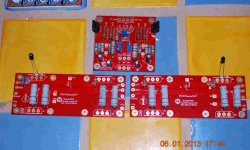
I got these in the mail yesterday and have been at them mostly since,
Check them over,
I am planing on 32 volt rails,around 15 volts for cascode,
I couldn't find the link about the link,Link to gnd?
Q5 and Q6 are correct with the silk ,are they backwards ?need to be turned around?
N out and P out switched on signal board,
any known issues?
I decide it was best to ask instead of smoking,,,,,,,,,😱😱😱
Thanks alot,
NoSmoking.........😀
Attachments
R5 has 4.22 volts across it. R6 has 4.55 V.
34 volt rails. No cascade going on.
I really appreciate the effort.
What V across source resistors of mosfets. Also, measure across gate and source of mosfets directly. 34V is pushing the Jfets id they are high Idss, but they are alive.
Hi Guys,
I got these in the mail yesterday and have been at them mostly since,
Check them over,
I am planing on 32 volt rails,around 15 volts for cascode,
I couldn't find the link about the link,Link to gnd?
Q5 and Q6 are correct with the silk ,are they backwards ?need to be turned around?
N out and P out switched on signal board,
any known issues?
I decide it was best to ask instead of smoking,,,,,,,,,😱😱😱
Thanks alot,
NoSmoking.........😀
Power up FE first and set drop across r5,r6 to 3.5V using P1 and P2. THis will allow you to figure out which way to turn the posts in order to adjust them. You will be starting at similar Vgs and will have solid footing for hooking up mosfets and firing them up.
Q5/Q6 is correct oriented on those boards. N-ch and P-ch is also correct.
Hi Guys,
I got these in the mail yesterday and have been at them mostly since,
Check them over,
I am planing on 32 volt rails,around 15 volts for cascode,
I couldn't find the link about the link,Link to gnd?
Q5 and Q6 are correct with the silk ,are they backwards ?need to be turned around?
N out and P out switched on signal board,
any known issues?
I decide it was best to ask instead of smoking,,,,,,,,,😱😱😱
Thanks alot,
NoSmoking.........😀
Q5/Q6 is correct oriented on those boards. N-ch and P-ch is also correct.
Oh, that sucks. All ok on your front.
What V across source resistors of mosfets. Also, measure across gate and source of mosfets directly. 34V is pushing the Jfets id they are high Idss, but they are alive.
P-ch
Source resistors: 136 mV
G-S: 4.06 V
N-ch
Source res: 139 mV
G-S: -4.38 V
Oh, that sucks. All ok on your front.
what sucks?
well. got my sinks cut tonight. so there will be some drilling and tapping tomorrow🙂 and if i'm lucky. there will be a power up🙂
P-ch
Source resistors: 136 mV
G-S: 4.06 V
N-ch
Source res: 139 mV
G-S: -4.38 V
If your maxed out on p1 and p2, then simply increase R5 and R6. You hove lower Idss Jfets and you just need higher load resistor, as AudioSan suggested, to bring up VGS for the mosfets. All is perfectly fine.
what sucks?
well. got my sinks cut tonight. so there will be some drilling and tapping tomorrow🙂 and if i'm lucky. there will be a power up🙂
Thought maybe you were suggesting possible routing error on output fets in beta board.
BTW, you may know this, but power drill with clutch set low, and some WD40 is excellent speedy tapping method.
- Home
- Amplifiers
- Pass Labs
- F5 Turbo Builders Thread