Audiosan, we want to see more boards complete, my advice: Go fast and take chances..
Love to see photos.
Love to see photos.
hehehe nrg 😀 i have one front end and 4 output boards finnished now🙂 maybe it will be sound over the weekend😀
BTW: all was soldered without looking at a bom or schematic🙂 i know this curcuit too well😀
BTW: all was soldered without looking at a bom or schematic🙂 i know this curcuit too well😀
THe F5 is a really tough design. I have been using the PSU to proto a J2 and once, when i hooked up the psu back to the F5T boards, I accidentally hooked up the positive wire to the output hole. Fried a fuse, nothing else, It is the perfect amp for first time builders. It just so happens, you get a phenominal amp. I can see the V3 competing against anything and have got a preliminary layout for a balanced version, to take advantage of excess current available at low rail voltages.
wow. you have realy taken it to the limit😀😀 i'm not a first time builder. i have a F5 on steroids allready😀
i have the balanced recepi in my head allready🙂 but i'm not going to build it. i stick with the good old single end🙂 i can handle the extra voltage😀
i have the balanced recepi in my head allready🙂 but i'm not going to build it. i stick with the good old single end🙂 i can handle the extra voltage😀
Last edited:
thats what i was thinking too. so i went for 16.4V🙂
one channel is finnished now. well, exept output fets and diodes.
just hoping i get the sinks cut tomorrow🙂
PSU or trans voltage ...? any boards at the store yet .... ?
wayne. 16.4V is the cascode voltage. rail voltage vil be around +/-51V with 2.5A bias.
no boards in the store yet. i use the first prototype boards from UKToecutter.
no boards in the store yet. i use the first prototype boards from UKToecutter.
I haven't heard from UKToecutter in a looong time. I hope he is doing well. He did a very nice job designing these boards..
nrg. he did a bond on us. a Aston martin vanish😀
he left the job half done, i'll know. i was the one rectifing the smal faults that was on the boards. alldoh i use those prototype boards on my monoblocks. it was only marking errors.
i'm just crossing my fingers and hope there is nothing else😀 i don't think there is. i have went thrue this curcuit and boards 100 times😀
Audiosan, you are on a large stage with many folks watching you and awaiting your results.
We need to keep our fingers crossed that it all works.. can you see any changes in layout at this point? I will read back in this thread and find the post with a photo of the boards.. i need to refresh my mind as to what they look like again..
We need to keep our fingers crossed that it all works.. can you see any changes in layout at this point? I will read back in this thread and find the post with a photo of the boards.. i need to refresh my mind as to what they look like again..
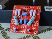
nrg. the big changes is that R3 and R4 has been 3W insted of 0.6W. and Q5/Q6 has been turned 180 degrees. and N-ch output and P-ch output has been switched🙂
nrg, funny you should ask
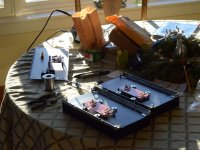
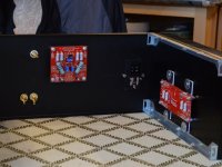
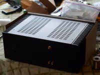
Finished wiring up a V2 monoblock last night. I am in the process of powering up the first time right now. I'm kinda guessing that P3 gets set near the middle of its range.
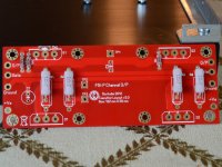
Anyhow, here are some photos. New UKToecutter boards, diyA chassis.
The plan is to get it up and running (biased) by tonight.
I'll post more details a bit later when I've got a spare moment and the amp's done.
-Nelson
Finished wiring up a V2 monoblock last night. I am in the process of powering up the first time right now. I'm kinda guessing that P3 gets set near the middle of its range.
Anyhow, here are some photos. New UKToecutter boards, diyA chassis.
The plan is to get it up and running (biased) by tonight.
I'll post more details a bit later when I've got a spare moment and the amp's done.
-Nelson
Attachments
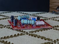
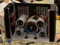
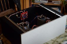
Mondo caps came from a Burning Amp raffle. I figured I'd use them because they fit and they were otherwise just sitting on the shelf.
33,000uF 60v each.
33,000uF 60v each.
Last edited by a moderator:

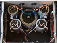
I'm in a spot of trouble. Here's what I spent the evening doing.
While trying to bias the above F5t channel I noticed a few problems.
I tested the power supply, it works fine, unloaded voltage hovers right around 35v.
I set P1 and P2 all the way counter-clockwise and P3 somewhere in the middle.
Power on and nothing smokes which is a good sign.
I measure voltage across R11 and R12. R11 is at 930 mV, R12 is close to zero.
Uh oh.
Turning P1 doesn't affect the voltage across R11. P2 adjusts R12 just fine.
Offset at the output was quite high, between 180 and 230 mV.
I say screw it, attach a test load and source and I get music. Why did that work?
Now I'm sitting here scratching my head. Best thing I can come up with is a transistor is gone. Neither P-ch heatsink or N-ch got any warmer than ambient using an infrared gun.
Anyone have something for me to measure or try?
Best,
Nelson
While trying to bias the above F5t channel I noticed a few problems.
I tested the power supply, it works fine, unloaded voltage hovers right around 35v.
I set P1 and P2 all the way counter-clockwise and P3 somewhere in the middle.
Power on and nothing smokes which is a good sign.
I measure voltage across R11 and R12. R11 is at 930 mV, R12 is close to zero.
Uh oh.
Turning P1 doesn't affect the voltage across R11. P2 adjusts R12 just fine.
Offset at the output was quite high, between 180 and 230 mV.
I say screw it, attach a test load and source and I get music. Why did that work?
Now I'm sitting here scratching my head.
Best thing I can come up with is a transistor is gone. Neither P-ch heatsink or N-ch got any warmer than ambient using an infrared gun. Anyone have something for me to measure or try?
Best,
Nelson
Reversed pot on one half?
Getting music out is possible even with a bit of bias. That's never the issue. The high offset is likewise normal indication because the adjustment process is about getting the bias and offset to hit a 'sweet spot'.
Getting music out is possible even with a bit of bias. That's never the issue. The high offset is likewise normal indication because the adjustment process is about getting the bias and offset to hit a 'sweet spot'.
Reversed pot on the half showing 0V?
That might be the case if the side showing zero was the one I'm worried about. It's t game e side at 930mV that isn't doing what it's supposed to. The pots are the correct orientation on the silk screen but I'll check the traces vs the schematic next.
- Home
- Amplifiers
- Pass Labs
- F5 Turbo Builders Thread