bk856er, that looks very good for a hand drill effort.
AudioSan, it can be done, but you need a lot of patience and experience, and also a very good fence on your table saw. There are a lot of other neat little tricks like an accurate crosscut sled and stop blocks that help, but that is a whole thread on it's own and since this is OT, I don't want to wander on this subject too long.
Maybe a new area in the Forum can cater for case construction and metalworking as a subject since is so tightly connected to building DIY audio equipment.
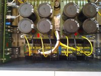
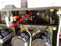
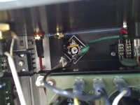
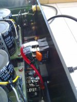
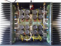
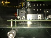
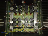
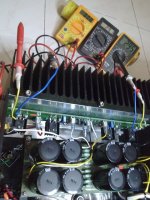
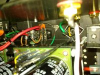
Here some pics of my build
First of all I would like to thank to the only "Nelson Pass" for his contribution toward DIY community. Special thanks to FM buzzforb for his help in getting semiconductor parts. jFETs are from spencers and passives are from element14 india, branch of farnell. Also thanking all of you who keep educating us.
I made few PCB for me and some friends of Indian forum. Last week built F5t v2 for a friend who has interest in music but not with hands on electronics.
Heatsinks are 83mm fins, 12mm gap, 12mm base thickness and 300mm X 150mm surface used for PCB mounting. Internal cabinet is 12" X 11". All metal work except heatsinks is done at home during weekends and given out for anodizing. Heatsinks were procured with proper finish, drilling and tapping done by local manufacturer.
Toroidal Transformer of 1KVA from local vendor with 4X24-0 secondaries used to power discrete rectifier board. There is one rectifier board which holds 16 MUR diodes and 32 noise suppressing film caps, making 4 discrete dual diode bridges. Four secondaries are getting into it giving 4 X (33V-0) DC. Each power filter board takes 2 X (33V-0) creating its own floating ground (AGND). This floating ground is connected to earth ground through isolators made from bridge rectifier blocks and 10Ω NTC. This we both the PS boards have separated ground reference. Caps are 4 X 15000µF /rail making total 120,000µF/channel .
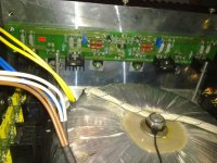
Four 5mm dia, 4" long bolts put around transformer which holds 2 aluminum U channels to attach filter PCB assembly keeping 3/4" gap in between transformer and PCBs. PCBs are double sided with ground plane at upper side. So its expected to provide some shielding to transformer.
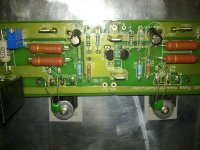
Rectifier board has diodes mounted from both th sides and its also mounted 50mm above bottom plate. On amplifier board I excluded P3.
Tried biasing 0.6A (300mV across source resistors) per device which was class 40W/ch (average). Finally another friend visited and was uncomfortable with heatsink temperature. So reduced bias so that source resistor dropped to 275mV. Cooked Amplifier with top lead and found its settled with output offset 5-6mV in each channel.
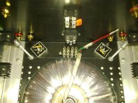
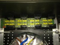
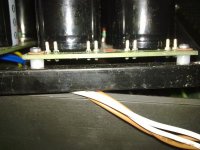
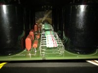
It is sounding nice.
First of all I would like to thank to the only "Nelson Pass" for his contribution toward DIY community. Special thanks to FM buzzforb for his help in getting semiconductor parts. jFETs are from spencers and passives are from element14 india, branch of farnell. Also thanking all of you who keep educating us.
I made few PCB for me and some friends of Indian forum. Last week built F5t v2 for a friend who has interest in music but not with hands on electronics.
Heatsinks are 83mm fins, 12mm gap, 12mm base thickness and 300mm X 150mm surface used for PCB mounting. Internal cabinet is 12" X 11". All metal work except heatsinks is done at home during weekends and given out for anodizing. Heatsinks were procured with proper finish, drilling and tapping done by local manufacturer.
Toroidal Transformer of 1KVA from local vendor with 4X24-0 secondaries used to power discrete rectifier board. There is one rectifier board which holds 16 MUR diodes and 32 noise suppressing film caps, making 4 discrete dual diode bridges. Four secondaries are getting into it giving 4 X (33V-0) DC. Each power filter board takes 2 X (33V-0) creating its own floating ground (AGND). This floating ground is connected to earth ground through isolators made from bridge rectifier blocks and 10Ω NTC. This we both the PS boards have separated ground reference. Caps are 4 X 15000µF /rail making total 120,000µF/channel .
Four 5mm dia, 4" long bolts put around transformer which holds 2 aluminum U channels to attach filter PCB assembly keeping 3/4" gap in between transformer and PCBs. PCBs are double sided with ground plane at upper side. So its expected to provide some shielding to transformer.
Rectifier board has diodes mounted from both th sides and its also mounted 50mm above bottom plate. On amplifier board I excluded P3.
Tried biasing 0.6A (300mV across source resistors) per device which was class 40W/ch (average). Finally another friend visited and was uncomfortable with heatsink temperature. So reduced bias so that source resistor dropped to 275mV. Cooked Amplifier with top lead and found its settled with output offset 5-6mV in each channel.


It is sounding nice.
Last edited:
Last edited:
Good work, omishra
What speakers/source are people using this amp with, for those who have completed it? Is it able to fill a medium-sized room with low sensitivity (~84-87dB) speakers? That was the one desiderata of the original F5.
What speakers/source are people using this amp with, for those who have completed it? Is it able to fill a medium-sized room with low sensitivity (~84-87dB) speakers? That was the one desiderata of the original F5.
I have 87dB and it handles them no problem. The f5t was created more for low impedance loads that needed big current.
That's great. I have 86dB speakers.
I assumed the higher voltage also gave a bit more output swing, as the original ran off 25V rails and had only 15dB gain. The turbo revised both those and that was my question.
If you're happy, I guess that's affirmative 🙂
I assumed the higher voltage also gave a bit more output swing, as the original ran off 25V rails and had only 15dB gain. The turbo revised both those and that was my question.
If you're happy, I guess that's affirmative 🙂
Thanks buzz and sangram.
Sangram, I tested this build with wharfedale 9.2 bookshelf 86 dB and GR research XLS encore supposed to be 87dB. Both worked well loud and clear.
Sangram, I tested this build with wharfedale 9.2 bookshelf 86 dB and GR research XLS encore supposed to be 87dB. Both worked well loud and clear.
Very, very nice!
You did the exact same thing with the analog ground and the earth as I did and as decribed by Nelson Pass.
Absolutely hum-free I guess?
😀
You did the exact same thing with the analog ground and the earth as I did and as decribed by Nelson Pass.
Absolutely hum-free I guess?
😀
Very, very nice!
You did the exact same thing with the analog ground and the earth as I did and as decribed by Nelson Pass.
Absolutely hum-free I guess?
😀
Thank you! You are correct. It is 100% free from hum and hiss. Even nothing could be heard while ear in front of drivers and no input attached. At my listening level during main power off, these PS cap keeping sound playing for almost 3-4 sec.
Last edited:
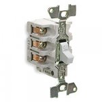
Anyone have some "cool" power switch suggestions for the front panel of a V2?
Push button round would be nice. I have been looking at Digikey but not really found anything.
Push button round would be nice. I have been looking at Digikey but not really found anything.
Easy😀
Ill try to find pics of what may maunfacturers use. It allows the button to be whatever you ca make.
Ill try to find pics of what may maunfacturers use. It allows the button to be whatever you ca make.
http://www.frozencpu.com/cat/l3/g44...ches-16mm_Latching_Bulgin_Switches-Page1.html
Problem is it's only rated 5amps. However, since it's latching, which is unusual for this type of switch, you could use a large non-latching relay....
They have non-latching too.
Problem is it's only rated 5amps. However, since it's latching, which is unusual for this type of switch, you could use a large non-latching relay....
They have non-latching too.
Last edited:
I bought this for another project, but it doesn't look as nice in real life as it does in the photos... but it works:
H8350RP-W Arcolectric | 1091-1057-ND | DigiKey
H8350RP-W Arcolectric | 1091-1057-ND | DigiKey
- Home
- Amplifiers
- Pass Labs
- F5 Turbo Builders Thread
