I think he is refering to the output diodes. And not the brigde rectifiers.
if that's the case. my recommendation is: Don't use them at all.
if that's the case. my recommendation is: Don't use them at all.
Last edited:
I agree. I did not use them in my V3 build. On a V3 in particular with 4 sets of outputs the diodes do not add much in terms of Db’s of output for most normal speaker loads. Even for V2 it is certainly not going to provide a big increase in dynamic range for a typical 4 or 8 ohm speaker load. I find that there have been reliability issues where some folks are trying to push the class A current up too close to the diode conduction point, resulting in some spectacular, expensive and disappointing meltdowns.
Hi Boys.
Thank You Cubicincher and Elwood.
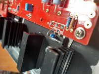
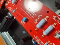
I moved termistor and change position onto the plastic.
Add little cap.
I set to "0" TP1 and TP2 (FE pcb) and I read the bias procedure but I haven't got all the instrumental and experience.
Now procede to assembly the case and after to fine set bias I'll ask to help from trusted techician.
Thank You Cubicincher and Elwood.
I moved termistor and change position onto the plastic.
Add little cap.
I set to "0" TP1 and TP2 (FE pcb) and I read the bias procedure but I haven't got all the instrumental and experience.
Now procede to assembly the case and after to fine set bias I'll ask to help from trusted techician.
Attachments
umut: The MUR30xx rectifiers specified in the original article have a conduction voltage that is only a hair above the idle bias setting.
Since the thermal compensation arrangement provides for the bias at startup to be higher than the final idle bias, there is a chance of the rectifiers conducting even without signal, which sends the output transistors into failure.
The few ways around this are
1) not to use any diodes at all
2) to use diodes with a higher knee voltage than the MUR3020 (which has the highest knee voltage of all that series)
3) to increase the source resistance to allow for a slightly higher safety margin (the bias 'voltage' needs to be recalculated in this instance)
The diodes you linked to have usefully higher knee voltage than the MUR3020, but only by a little bit. This makes me optimistic about most of them, but you will still need to feel your way around the circuit.
If possible, use a current-limited power supply (say 2A) to work out what bias points you can set with the diodes and a few combinations of the source R. With a knee voltage of just around 0.6V, you can probably target around 0.56 ohms source R (that's 4x 2.2ohm resistors) for a standing bias around 1.6A - a bias voltage of around 0.45V. This should give you some margin to safety and all the benefits of the full Turbo experience. The diodes will start conducting only when the output current reaches about 2.5A.
If that sounds like too much trouble, just drop the diodes.
Just to be clear, you only need one diode, a few resistors and a benchtop power supply (or a CCS with a big heatsink) to work the combinations out. The actual circuit is not even needed for the initial discovery.
So got the transformers back in the amps with windings varnished and extra turns to reduce the output voltage. Mechanical hum is defiantly quieter, mainly the harmonics have been removed. Not sure the extra windings make much difference to the mechanical noise, will try with them bypassed next time I have time.
Can't hear the mechanical hum from the listening seat, but still quite noticabe when stood next to them. No noise through the speakers, just great sounding sweet music. Only 40degC on hottest part of heat sink, so room for more bias.
Maybe time to try a DC blocker to get rid of mechanical hum.
Can't hear the mechanical hum from the listening seat, but still quite noticabe when stood next to them. No noise through the speakers, just great sounding sweet music. Only 40degC on hottest part of heat sink, so room for more bias.
Maybe time to try a DC blocker to get rid of mechanical hum.
Attachments

So I’m sure this has been asked but don’t have time to read all posts. Has anyone looked at SMPS for this amp. How do you get bipolar supplies? Connect two at midpoint. Can you even do that?
It's not a very good solution for this amplifier. You can use two 36V supplies in series, but since the amps have a very large difference between peak output current and continuous idle draw, you'd be better served with a supply that can handle current swings. SMPS are best suited for loads that draw continuous current, or close enough - SE amps like the ACA or VFET are a better match.
Meanwell has some 350W models that might be a good bet, if you're targeting cost or power savings. If you don't use too much power you should be okay. For push-pull amplifiers the load on each SMPS will be twice the idle current when staying within the Class A envelope.
Meanwell has some 350W models that might be a good bet, if you're targeting cost or power savings. If you don't use too much power you should be okay. For push-pull amplifiers the load on each SMPS will be twice the idle current when staying within the Class A envelope.
So I was actually looking at two 500 watt supplies. Do use those directly connected to amp or do you run external filters on the output of SMPS. If so doesn’t that create other problems for supplies
An external LC filter helps, but slows down the transient response of the supply even further (which is what makes this sort of supply suboptimal). You can try a cap multiplier with a MOSFET, but then you'll need additional supply headroom + additional heat from the MOSFETs. I'm not sure it's a worthwhile tradeoff.
Having said all of this, I still have at least three amplifiers running off SMPS. They do work, but a linear supply is better when you're pushing low loads, high output levels and a Class A standing bias. An external cap bank may or may not work (without inductors). The few times I've used have been fairly decent, no hiccups from the supplies.
Having said all of this, I still have at least three amplifiers running off SMPS. They do work, but a linear supply is better when you're pushing low loads, high output levels and a Class A standing bias. An external cap bank may or may not work (without inductors). The few times I've used have been fairly decent, no hiccups from the supplies.
Ok so it sounds like your leaning toward linear. Does it make a difference if my load is minimum 8 ohm and most of the time around 10 ohm? Only other thing is the speaker sensitivity is 84 db range.
At 36V rails a 500W supply is capable of 13.8A. This is quite a bit and is sufficient for most applications if viewed in isolation, but for a 50Khz bandwidth you need the supply to have very fast recovery, which might not be possible because for most commercial SMPS the switching frequency is around 65-80KHz.
Output current by itself is not the issue, but the speed at which the supply needs to respond to transient demands, is very much a problem. You could try it and see, there's no harm if you already have the supplies. One advantage of SMPS is that they significantly improve total efficiency from the wall, so some might still find them advantageous in certain situations.
Besides, the deficiencies come into play at higher levels, which you may or may not ever actually reach.
Ok I have everything for a linear supply so sounds like I should go that way. But I want to fully understand the operation. I thought that being class A even a push pull I would have a constant current draw on each half of the output transistors. By definition 360 degree conduction per output. So how exactly does it deviate from this?
At idle, both a PP and SE amp of any operating Class will draw a constant current. Let us assume this is 1A for a Class A amplifier.
With no signal going in, there is no current through the load and the total power supply current is flowing from the upper transistor +VE supply to the lower transistor -VE supply.
When you apply a positive signal at the input, the lower transistor will start moving towards cutoff. The current will now 'reroute' through the load, thus increasing the current draw at positive rail.
The supply does see the total current to be the same, as you rightly pointed out - the key word being 'supply', the singular. But when the two supply halves are supplied by two different power supplies, the load on one will decrease while the load on the other one increases.
So I understand what you are saying about the power supply. That would be the same scenario with a linear with 2 secondary windings for bipolar operation correct? So can a class A pull more current than the idle current or in case of PP CA 2X idle current?
At any point when you connect the common, the transformer primary is what looks at the actual load through the core. So no, it is not exactly the same thing. If you had two transformers, one generating each rail, then the same scenario would apply as for the two SMPS.
- Home
- Amplifiers
- Pass Labs
- F5 Turbo Builders Thread