Agree, sounds like your P-channels are gone too.
I believe Audiosan meant you should check if there is continuity between fets and sink, iow if any if the new thermal pads are broken/have bits of metal conducting to case.
But do you have a working theory as to why it happened? I would make sure it does not happen again. Can it be due to some of those changes you made? It sounds to me like that’s a probable working theory, which should be solved before replacing fets.
What are your own thoughts as to the cause of it all?
Btw: your build looks great, man.
Cheers,
Andy
Last edited:
Andy:
While further guidance would be appreciated before I tear into the P side of the amp, I do have a working (and possibly strained) theory:
The Keratherm insulators are paper thin. The AI203 insulators that replaced them are 0.6mm thick, and there's a very thin smear of Kryonaut thermal paste between the insulators and the heatsink. I didn't remove the MOSFETs or MUR3020 diodes from any of the O/P boards when replacing the insulators, so they may have been stressed when removing them from the heatsinks and, after the AI203s were installed, the gap between the MOSFETs (and diodes) and the O/P boards was reduced by a little over a half-millimeter. My theory is that the removal and/or that reduction put new stress on whatever the MOSFETs legs tie to inside the MOSFET.
Beyond that, I got nothing.
So, does anyone else have a suggestion other than replacing the P-channel MOSFETs?
Many, many thanks,
Scott
Last edited:
smallest enclosure for this amp?
I'm curious what is the smallest enclosure anyone has made this amp in.? I'm doing my first advanced build in a "Ultimate 4U 500mm" case, and it seems too big - it's nice to have space, but it could lose 2 in in all dimensions and be fine - cooling heatsink aside of course.

I'm curious what is the smallest enclosure anyone has made this amp in.? I'm doing my first advanced build in a "Ultimate 4U 500mm" case, and it seems too big - it's nice to have space, but it could lose 2 in in all dimensions and be fine - cooling heatsink aside of course.
primary and secondary transformer wire hook ups
1. How do I use the Cascode Forumula with 25V rails to come up with a good cascode voltage?
2. Should I ignore the #3 (18V) and #4 (12V) output wires on the transformer
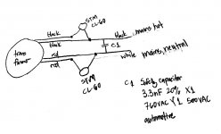
3. I noticed the "in rush" capacitors (STM CL-60) are only hooked up to one of the sides of the In Put on the transformer. How does that work exactly? Wouldn't one side get slow, vs one side fast "in rush" current? Or is it the Hot on one side, and the Neutral on the other? If so, how do you identify which is which?
https://www.mouser.com/ProductDetail/72-AY1332M57Y5UC63L0/
https://www.mouser.com/ProductDetail/527-CL60/
I'm doing an F5T. I was planning on 32v rails, but the transformer I got won't make that possible.
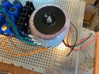
The transformer is an Antek AN-8225, 800VA 25V transformer. It has two 25V outputs, as well as an 18V and 12V (I transcribed the sticker on the side of it below).
Printed on the side of the transformer is:
I/P 1. 115V 50/69Hz RED-BLACK
2. 115V 50/60Hz RED-BLACK
O/P 1. 25V BLUE-GREEN
2. 25V BLUE-GREEN
3. 18V BROWN-BROWN
4. 12V ORANGE-ORANGE
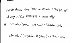
I took a peek at the "cascode formula" from the BOM for DIY Audio F5 Turbo, but I'm not sure what I'm shooting for here. I see folks talking about the formula, and cascode voltages, but not a lot of actual equation writing out. I'd like to understand this a little more.
When I was planning for 32V rails, (should got an AN-6432 32V 600VA transformer), I was advised to use 4.7kOhm for R25, 26, 27,and R28. That equation would come out to 12.5V for cascode voltage.
But what do I do or want with that number? This youtube video about "The Basics of Cascode Amplifer and Miller Effect" is above my head!
The example equation of the Cascode Formula uses 50V rails. Perhaps I could make that happen by hooking up the two Out/Puts in series - then the amps would be twice as high as a parallel hookup that I think others have used.
My power supply has 8x 22,000µF capacitors (digikey 4787PHBK-ND) total: 176,000 µF
1. How do I use the Cascode Forumula with 25V rails to come up with a good cascode voltage?
2. Should I ignore the #3 (18V) and #4 (12V) output wires on the transformer
3. I noticed the "in rush" capacitors (STM CL-60) are only hooked up to one of the sides of the In Put on the transformer. How does that work exactly? Wouldn't one side get slow, vs one side fast "in rush" current? Or is it the Hot on one side, and the Neutral on the other? If so, how do you identify which is which?
https://www.mouser.com/ProductDetail/72-AY1332M57Y5UC63L0/
https://www.mouser.com/ProductDetail/527-CL60/
I'm doing an F5T. I was planning on 32v rails, but the transformer I got won't make that possible.
The transformer is an Antek AN-8225, 800VA 25V transformer. It has two 25V outputs, as well as an 18V and 12V (I transcribed the sticker on the side of it below).
Printed on the side of the transformer is:
I/P 1. 115V 50/69Hz RED-BLACK
2. 115V 50/60Hz RED-BLACK
O/P 1. 25V BLUE-GREEN
2. 25V BLUE-GREEN
3. 18V BROWN-BROWN
4. 12V ORANGE-ORANGE
I took a peek at the "cascode formula" from the BOM for DIY Audio F5 Turbo, but I'm not sure what I'm shooting for here. I see folks talking about the formula, and cascode voltages, but not a lot of actual equation writing out. I'd like to understand this a little more.
When I was planning for 32V rails, (should got an AN-6432 32V 600VA transformer), I was advised to use 4.7kOhm for R25, 26, 27,and R28. That equation would come out to 12.5V for cascode voltage.
But what do I do or want with that number? This youtube video about "The Basics of Cascode Amplifer and Miller Effect" is above my head!
The example equation of the Cascode Formula uses 50V rails. Perhaps I could make that happen by hooking up the two Out/Puts in series - then the amps would be twice as high as a parallel hookup that I think others have used.
My power supply has 8x 22,000µF capacitors (digikey 4787PHBK-ND) total: 176,000 µF
Attachments
Answer to two of the questions: With 25v rails you do not need cascode. The JFETs are rated at 25 volts. Less is more. With 25v rails NO First Watt amps have cascode.
With 25 volt rails I would also like to add you will probably loose a lot of the Turbo. With 25v rails I would have rather built an ordinary F5.
On 120v primaries (US) there are 2xCL60. On 240v (Europe) just 1. It does not slow anything down other than what it is supposed to: the inrush current.
Why not go for 32v rails and live happily?
Cheers,
Andy
Last edited:
1. How do I use the Cascode Forumula with 25V rails to come up with a good cascode voltage?
See post 6014/6015 for where you'll potentially wind up, but you'll have closer to 33+VDC rails depending on your mains voltage and what you're using for bridges, the load etc. See below.
2. Should I ignore the #3 (18V) and #4 (12V) output wires on the transformer
Yep
3. I noticed the "in rush" capacitors (STM CL-60) are only hooked up to one of the sides of the In Put on the transformer. How does that work exactly? Wouldn't one side get slow, vs one side fast "in rush" current? Or is it the Hot on one side, and the Neutral on the other? If so, how do you identify which is which?
Those are thermistors, not capacitors. You have it drawn similar to a standard "First Watt" PSU for 120VAC mains, which has one thermistor on the hot side and one on the neutral. The F5T schematic shows one thermistor on the hot side. There is some discussion re: the pros and cons of either method in the Universal PSU thread. Summarizing though, no, one "side" won't go faster or slower. Also, Mark Johnson gives a really nice explanation of current vs. operating temperature and expected "hot resistance" and performance that I could (mostly) absorb in his thread for CL-60 alternatives.
They work to limit inrush b/c they have a higher resistance cold. When they get hot, the resistance lowers.
You identify the hot and neutral from your wall outlet. You can connect the red or black primary leads to hot. It makes no difference, but convention (I think) with Anteks is to use black to hot. Hot per the schematic is noted by "120".
I'm doing an F5T. I was planning on 32v rails, but the transformer I got won't make that possible.
Sure it will. 😉 Rails are DC. Transformer is AC. Roughly ~25VACx1.4=~35VDC after rectification.
The transformer is an Antek AN-8225, 800VA 25V transformer. It has two 25V outputs, as well as an 18V and 12V (I transcribed the sticker on the side of it below).
Printed on the side of the transformer is:
I/P 1. 115V 50/69Hz RED-BLACK
2. 115V 50/60Hz RED-BLACK
O/P 1. 25V BLUE-GREEN
2. 25V BLUE-GREEN
3. 18V BROWN-BROWN
4. 12V ORANGE-ORANGE
You have a 8425. Doesn't really matter, but that's what you have. 8225 only has 25VAC secondaries. 8425 has the "extra" 18V and 12V.
I took a peek at the "cascode formula" from the BOM for DIY Audio F5 Turbo, but I'm not sure what I'm shooting for here. I see folks talking about the formula, and cascode voltages, but not a lot of actual equation writing out. I'd like to understand this a little more.
When I was planning for 32V rails, (should got an AN-6432 32V 600VA transformer), I was advised to use 4.7kOhm for R25, 26, 27,and R28. That equation would come out to 12.5V for cascode voltage.
Nope. See above re: calculation for rough expected DC and the posts for cascode calcs for those rails. 32VAC would give you ~43+VDC rails.
But what do I do or want with that number? This youtube video about "The Basics of Cascode Amplifer and Miller Effect" is above my head!
Don't worry about it then. It's above my head too. The purpose is to not fry your JFETs. 😀 See the article starting about here...
"The more technically astute DIYer may note that the input Jfets are now
being exposed to greater voltage and dissipation, and this might be a
concern...."
The example equation of the Cascode Formula uses 50V rails. Perhaps I could make that happen by hooking up the two Out/Puts in series - then the amps would be twice as high as a parallel hookup that I think others have used.
Don't do that.
My power supply has 8x 22,000µF capacitors (digikey 4787PHBK-ND) total: 176,000 µF
Those are 40V caps. If you can swing it in your budget, maybe consider 50V caps. Not strictly needed, but if you ever decide you do want to use the PSU for a "hotter" amp with higher rails, you can.
tl;dr - It seems you're good to go.
BTW - totally separate topic, but I think I saw a pic of your Ultimate 4U/500 in another thread. If I did, GORGEOUS front panel. 😀 I'm jealous, mine are still stuck in Memphis.
Last edited:

Folks:
Thank you (especially AudioSan, once again), for your guidance! Replacing the P-channel MOSFETs did the trick. My F5T monoblocks are up and running, sounding terrific and more authoritative than the lovely, rounded F6 that I use as a back-up.
My go-to track for all new and repaired components is Be Bop Deluxe's Shine, off their "Live! In the Air Age" album (not the version added as a bonus track to the remastered "Modern Music" CD). Highly recommended if you like soaring guitar solos.
I'm so glad the F5Ts are back -- what a relief!
Regards,
Scott
Hello again! I think I'd like my signal runs from the back panel in and out of the amplifier boards to be shielded, maybe using some type of coaxial cable. I'm wondering if anybody has recommendations for specific types of wire to use for these runs. Thanks!
I'm so glad the F5Ts are back -- what a relief!
Happy to hear you have them back up and running.

to SRMcGee #6428
Keep the F5-Ts alive!
They make so beautiful music...
I love my F5-T - Monoblocks too.
Greets
Dirk 😀
Keep the F5-Ts alive!
They make so beautiful music...
I love my F5-T - Monoblocks too.
Greets
Dirk 😀
recommendations!
Mogami 2520
Very nice to work with (they‘re 2.3mm thin, extremely flexible, soft to the touch, easy to strip, and they sound very transparent, clean and neutral...)
Mogami 2803 is said to be the best of all (soundwise), this is a impressive cable, but nearly impossible to use for internal wiring because it’s really stiff. (You can’t bend it below a radius of ca 5 cm, and you‘d have to hold it to avoid stressing the connections)
Awesome, thanks! I asked the same question elsewhere and was recommended Belden 8529 recommended to me, which I guess is 50ohm RG-58, would this be good to use?
Unrelated, I have some scraps of Keratherm left over, would it be OK to use these between the transistors on the input boards instead of just heat compound? Or would the electrically insulating property of the Keratherm be a negative? It's my understanding that the transistors are mated strictly for thermal stability, but maybe I'm missing something. What do y'all think?
Thanks again!
Last edited:
F5 Turbo v1
Good morning,
I'm writing from Italy.
I started my F5 Turbo. I decided to bulit F5 turbo v1.
I have need help to set bias. I found set bias F5 v2. I would to know if there is different value and method between version V1 and V2.
I'm using hiFi200 case, the biggest 4U, is it sufficient?
Thank You
Good morning,
I'm writing from Italy.
I started my F5 Turbo. I decided to bulit F5 turbo v1.
I have need help to set bias. I found set bias F5 v2. I would to know if there is different value and method between version V1 and V2.
I'm using hiFi200 case, the biggest 4U, is it sufficient?
Thank You
Attachments


Excuse me I forgot and then I add....
I've possibiliy to bult V2, my case is it sufficient?
1000 thank
nicola
I've possibiliy to bult V2, my case is it sufficient?
1000 thank
nicola
No questions this time, just wanted to point out what an idiot I am - I thought there was a bit more overlap between the F5 Parts Kit sold here in the store and the F5T v2/3 BOMs...was sat here last night for longer than I'd care to admit, looking back and forth between the F5T BOM and the F5 Parts Kit BOM like, "wait a minute, something's wrong here..." 🙄
grounding PSU
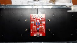
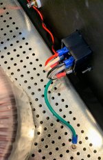
Grounding on the PSU board. Looks like there are loads of grounds there: at the capacitor side DC side of the board: GND, GND1, GND2*, then other side (tied together): GND3, GND4, and GND5*. I've got a couple spades soldered to ST_G1 and ST_G2*. Figured I'd wire both of those with a green wire to the perforated steel floor of the amp. The inlet IEC outlet ground (AC) is also wired to that ground.
I can't find a specific spot in the F5Turbo Illustrated Build Guide where 6L6 mentions the grounding of the PSU board. The board in the "DIY Audio Power Supply Circuit Board V3" has the diode section busted off there, and looks different.
6L6 has couple black wires coming off GND2.2 and ST_G1 (same), going off frame, and a couple green ones coming out of V- and V--, also going off frame.
I'm looking at the "diyAudio PSU board v3.0" schematic, and the GNDXXs are going to X.
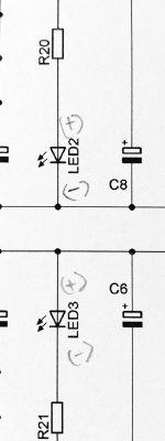
Also a little odd: the "D--1", "D-1", and "D+2", "D++2" are both going to ground. This is more of my misunderstanding of what's happening. The LED2 and LED3, on the diagram* aren't a mirror image. LED3 seems to have its anode (+) attached to ground. A while back 6L6 pointed out I had my LEDs backwards, that one side was more negative than the other. This is what he was talking about? As I soldered them down, I figured the center of the board was ground, and wired both LED cathodes to that side: a mirror image of each other. By the schematic and what I did, I expect LED2 to work, and LED3 to fry. It also seems odd that the R21 would be on the (-) cathode side, where the LED2 (+) anode has the R20 in front of it.
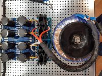
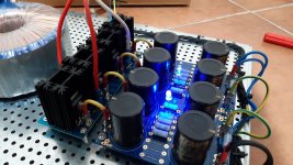
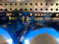
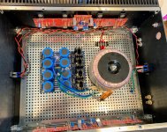
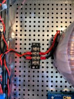
I threw a few other pics in there to see if any red flags come up for the community. I'm about two hours away from hooking the PSU up this variac and <hoping> correct measurements pop out the other side w/out sparks and smoke. The safety cap, and CL-60s will be added to the connector barrier strip as soon as I get them. This is not final configuration, just want to see if I got Joy here.
*pic attached
Grounding on the PSU board. Looks like there are loads of grounds there: at the capacitor side DC side of the board: GND, GND1, GND2*, then other side (tied together): GND3, GND4, and GND5*. I've got a couple spades soldered to ST_G1 and ST_G2*. Figured I'd wire both of those with a green wire to the perforated steel floor of the amp. The inlet IEC outlet ground (AC) is also wired to that ground.
I can't find a specific spot in the F5Turbo Illustrated Build Guide where 6L6 mentions the grounding of the PSU board. The board in the "DIY Audio Power Supply Circuit Board V3" has the diode section busted off there, and looks different.
6L6 has couple black wires coming off GND2.2 and ST_G1 (same), going off frame, and a couple green ones coming out of V- and V--, also going off frame.
I'm looking at the "diyAudio PSU board v3.0" schematic, and the GNDXXs are going to X.
Also a little odd: the "D--1", "D-1", and "D+2", "D++2" are both going to ground. This is more of my misunderstanding of what's happening. The LED2 and LED3, on the diagram* aren't a mirror image. LED3 seems to have its anode (+) attached to ground. A while back 6L6 pointed out I had my LEDs backwards, that one side was more negative than the other. This is what he was talking about? As I soldered them down, I figured the center of the board was ground, and wired both LED cathodes to that side: a mirror image of each other. By the schematic and what I did, I expect LED2 to work, and LED3 to fry. It also seems odd that the R21 would be on the (-) cathode side, where the LED2 (+) anode has the R20 in front of it.
I threw a few other pics in there to see if any red flags come up for the community. I'm about two hours away from hooking the PSU up this variac and <hoping> correct measurements pop out the other side w/out sparks and smoke. The safety cap, and CL-60s will be added to the connector barrier strip as soon as I get them. This is not final configuration, just want to see if I got Joy here.
*pic attached
Attachments
Last edited:
Hope it all worked out as expected yesterday.
For just your PSU test, you don't need to have the "Audio" ground connected.
Once you're ready to hook up the amp boards and ground lift etc... The multiple GND points on the PSU boards are for versatility. Any of them will be fine. The F5T PSU schematic shows a diode bridge + thermistor for the ground lift. A typical implementation would be to have one side to any one of the GND points on your PSU board and the other side to chassis / earth.
re: the LEDs. tl;dr, yes, that's what 6L6 was likely explaining, but I don't have the original post to reference. R20 and R21 limit the current through the LEDs, and their relative position between GND and the LED doesn't matter. The LED anode needs to be connected to the "more positive" side of the voltage supply to work, which for the negative rail would be GND.
Not to sound silly, but assume you have a functioning PSU and you measure -35VDC when the "black probe" of your DVM is on GND and the "red probe" is on V-. If you reverse your DVM leads (red to GND and black to V-), what would it measure, and how would you orient the LED? Does that mental picture help?
Separately, you mentioned this wasn't permanent, but I'd consider moving your AC lines to the middle of your chassis further away from your left channel boards and your output.
- Home
- Amplifiers
- Pass Labs
- F5 Turbo Builders Thread