What is the best values for cascode resistors at 32V supply? Now i have 10k for R25, R26 and 4,75k for R27, R28 wich give me 10.3V.
If i would like to have ca. 13.2V, is it ok to use 6,8k resistors for R25, R26 or i must change the R27 and R28 too?
If i would like to have ca. 13.2V, is it ok to use 6,8k resistors for R25, R26 or i must change the R27 and R28 too?
to a007udio
Hello a007udio,
railvoltage / (R26+R28) x R28 = cascode voltage.
32V / (6800 Ohm + 4750 Ohm) x 4750 Ohm = 13.16 V cascode voltage.
You can go up to 16 V cascode voltage (F5T V3!) if I remember right...
32 V / (4750 Ohm+ 4750 Ohm) x 4750 Ohm = 16.17 V cascode voltage.
I hope I made no mistake....🙄
Greets
Dirk 😀
32/(10+6.8)*6.8=12.95V
you could also use 10K for all and get
32/(10+10)*10=16V.
EDIT: I see i calculated R27/R28 as 6.8Kohm and left R25/R26 10Kohm 🙂
you could also use 10K for all and get
32/(10+10)*10=16V.
EDIT: I see i calculated R27/R28 as 6.8Kohm and left R25/R26 10Kohm 🙂
Last edited:
Two PSU from one Transformer
Hi,
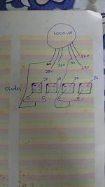
Please help confirm if connection in image is good.
Transformer is 1000VA ( Transformer secondary wires are 2.5 sq mm)
0-28-36
0-28-36
Diode - GBPC3506 - four
Need to run two different PSU from same transformer(different voltages)
Is it fine to to connect 0V wire to two diodes as show in Image. This is for F5T v2 and Aleph2 (Mono) fed from same transformer.
Thank you
Hi,
Please help confirm if connection in image is good.
Transformer is 1000VA ( Transformer secondary wires are 2.5 sq mm)
0-28-36
0-28-36
Diode - GBPC3506 - four
Need to run two different PSU from same transformer(different voltages)
Is it fine to to connect 0V wire to two diodes as show in Image. This is for F5T v2 and Aleph2 (Mono) fed from same transformer.
Thank you
Attachments
Last edited:
My plan is to add 12.1k resistor in parallel to R25, R26 to get 5.47k.
32/(4.75+5.47)*4.75=14.86V
Sound good?
32/(4.75+5.47)*4.75=14.86V
Sound good?
It is railvoltage/(R25+R27)*R27
and railvoltage/(R26+R28)*R28
And yes, that wil work. But why not just use 10K or 4.75K for all and get 16V?
and railvoltage/(R26+R28)*R28
And yes, that wil work. But why not just use 10K or 4.75K for all and get 16V?
Last edited:
When installing the P and N channel MOSFETs on the first channel I mistakenly thought IRFP9240 matched FQA19N20, but it actually matches FQA12P20. I didn't realize the 9 switched channels between the two model names. Thankfully when I went to populate the second channel I noticed, before too late. Hopefully I haven't made other, unnoticed errors. I'll find out soon enough, hoping to have it fully assembled some time this weekend finally. Started this project back in January, but got super busy and had to put it on hold for a while. Still having fun, but definitely ready to be done. Between misunderstandings, mistakes, modifications, customizations, and a number of other factors, my sweat equity on this thing is through the roof. I'm sure that the finished amp will sound all the better to my ears for it.
When installing the P and N channel MOSFETs on the first channel I mistakenly thought IRFP9240 matched FQA19N20, but it actually matches FQA12P20. I didn't realize the 9 switched channels between the two model names. Thankfully when I went to populate the second channel I noticed, before too late. Hopefully I haven't made other, unnoticed errors. I'll find out soon enough, hoping to have it fully assembled some time this weekend finally. Started this project back in January, but got super busy and had to put it on hold for a while. Still having fun, but definitely ready to be done. Between misunderstandings, mistakes, modifications, customizations, and a number of other factors, my sweat equity on this thing is through the roof. I'm sure that the finished amp will sound all the better to my ears for it.
Got most of the way there today. Still need to connect the amp boards to the PSUs and back panel ports. Just powered up the Soft Start and PSUs and am getting ±33.6V per rail. Apparently I have the LED on the positive channel of one power supply backwards however. Hope to be through biasing tomorrow, barring further errors.
Got most of the way there today. Still need to connect the amp boards to the PSUs and back panel ports. Just powered up the Soft Start and PSUs and am getting ±33.6V per rail. Apparently I have the LED on the positive channel of one power supply backwards however. Hope to be through biasing tomorrow, barring further errors.
Got through initial biasing. Going to test on speakers tomorrow and then let it play for about a week before final-checking bias and calling it done.
When installing the P and N channel MOSFETs on the first channel I mistakenly thought IRFP9240 matched FQA19N20, but it actually matches FQA12P20. I didn't realize the 9 switched channels between the two model names.
Oooo can you tell me about this in more detail? I’m going to need to triple check all my MOSFETs. The chips I got are
IRFP9240
IRFP240
SDUR60P60WT
TIP31AG
TIP32AG
That is a subtle difference there with that 9 in there. I wonder if I missed that one too. From the BOM details below, both Q3 and Q4 are IRFP9240, and both Q5 and Q6 are IRFP240.
From BOM
Q3, Q4 = IRFP9240, FQA12P20 or equal
Q5, Q6 = IRFP240, FQA19N20 or equal
So glad to hear it’s coming together! Regarding the leds on the power supply unit, I had my backwards for a minute too. Take a close look at the PSU schematic. The digram has the triangle with the line and they both point the same way. I figured the would point opposite directions. Just double check internets for anode cathode diagrams, long leg short leg, and stick to the schematic.
And on one other note, I’m going to PM ya!
to Mrdrewk #6490
Hello Mrdrewk,
normally you use IRFP240 (N-channel) and IRFP9240 (P-channel) devices together
or FQA19N20 (N-channel) and FQA12P20 (P-channel) together.
Make sure, that you put them into the correct place on your outputboards! 🙄😱
Greets
Dirk😀
Hello Mrdrewk,
normally you use IRFP240 (N-channel) and IRFP9240 (P-channel) devices together
or FQA19N20 (N-channel) and FQA12P20 (P-channel) together.
Make sure, that you put them into the correct place on your outputboards! 🙄😱
Greets
Dirk😀
Last night I powered up the amp for the first time, and was able to bias all channels up to ~350mV with DC offset seemingly stable around 0. I didn't have any dummy loads or anything, so nothing was connected to the inputs or outputs. The amp was on for just about 12 hours and was power-cycled several times, all good.
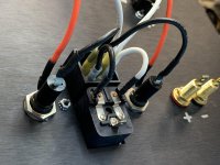
This morning I plugged in my test speakers and some RCA inputs, but the moment I flipped the switch it looks like I blew a fuse. I used the fuses sold in the back panel kit. The one that blew was an F2AL250V, which I had on the hot side of the IEC block. The fuse on the other side says 10A250V, so significantly higher amp rating than the one that blew. Did I have them placed backwards, maybe the 10 should have been on the hot side? Should the two fuses be the same model, or is using two different fuses by design? Or since the 2amp fuse blew maybe I have an issue somewhere?
I'm running dual mono with two Universal PSUs, each fed by their own Antek AN-6224 transformer, with a Soft Start in front of them. Maybe I just need beefier fuses to handle this much juice?
The 10A MUST stay on the neutral.
Your other fuse is too small for that much PSU. Try A 3A slo blow. If that doesn’t hold, increase by .5A until it does.
Your other fuse is too small for that much PSU. Try A 3A slo blow. If that doesn’t hold, increase by .5A until it does.
Last night I powered up the amp for the first time, and was able to bias all channels up to ~350mV with DC offset seemingly stable around 0. I didn't have any dummy loads or anything, so nothing was connected to the inputs or outputs. The amp was on for just about 12 hours and was power-cycled several times, all good.
This morning I plugged in my test speakers and some RCA inputs, but the moment I flipped the switch it looks like I blew a fuse. I used the fuses sold in the back panel kit. The one that blew was an F2AL250V, which I had on the hot side of the IEC block. The fuse on the other side says 10A250V, so significantly higher amp rating than the one that blew. Did I have them placed backwards, maybe the 10 should have been on the hot side? Should the two fuses be the same model, or is using two different fuses by design? Or since the 2amp fuse blew maybe I have an issue somewhere?
I'm running dual mono with two Universal PSUs, each fed by their own Antek AN-6224 transformer, with a Soft Start in front of them. Maybe I just need beefier fuses to handle this much juice?
You need more than a 2 amp fuse I reckon. I use dual 6A slow blow fuses. Seems to work fine.
The 10A MUST stay on the neutral.
Your other fuse is too small for that much PSU. Try A 3A slo blow. If that doesn’t hold, increase by .5A until it does.
You need more than a 2 amp fuse I reckon. I use dual 6A slow blow fuses. Seems to work fine.
This is exactly the advice I was looking for, and what I was hoping to hear. Huge thanks! Back to the hardware store I go!

I had the same problem. Mine because I didn't let the amp cool off enough before turning it back on again (similar to your scenario). I also used the 10A FB glass fuses that came with the IEC plug. I chose to use separate fuse holders after that since I built with dual PSUs. I chose 4A SB for those since that's what was in the Aleph J service manual. I haven't looked too intently at the F5 manual to see what was recommended. But the above advice is good. 🙂
Last night I powered up the amp for the first time, and was able to bias all channels up to ~350mV with DC offset seemingly stable around 0. I didn't have any dummy loads or anything, so nothing was connected to the inputs or outputs. The amp was on for just about 12 hours and was power-cycled several times, all good.
This morning I plugged in my test speakers and some RCA inputs, but the moment I flipped the switch it looks like I blew a fuse. I used the fuses sold in the back panel kit. The one that blew was an F2AL250V, which I had on the hot side of the IEC block. The fuse on the other side says 10A250V, so significantly higher amp rating than the one that blew. Did I have them placed backwards, maybe the 10 should have been on the hot side? Should the two fuses be the same model, or is using two different fuses by design? Or since the 2amp fuse blew maybe I have an issue somewhere?
I'm running dual mono with two Universal PSUs, each fed by their own Antek AN-6224 transformer, with a Soft Start in front of them. Maybe I just need beefier fuses to handle this much juice?
Attachments
This is exactly the advice I was looking for, and what I was hoping to hear. Huge thanks! Back to the hardware store I go!
3A slow blow seems to be doing the trick. I am currently hearing music out of my speakers. Sweet holy heck, I think I did it!!! 😎
Massive thanks to everybody here, especially 6L6 and all the other frequent commenters. Too many people have helped me to name you all, but you know who you are, pat yourself on the back. It takes a village to make an F5Turbo, as the saying goes.

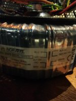
So got the transformers back in the amps with windings varnished and extra turns to reduce the output voltage. Mechanical hum is defiantly quieter, mainly the harmonics have been removed. Not sure the extra windings make much difference to the mechanical noise, will try with them bypassed next time I have time.
Can't hear the mechanical hum from the listening seat, but still quite noticabe when stood next to them. No noise through the speakers, just great sounding sweet music. Only 40degC on hottest part of heat sink, so room for more bias.
Maybe time to try a DC blocker to get rid of mechanical hum.
Hummmm.
Can anyone recommend a transformer that doesn't make mechanical hum noise when the mains voltage is 240V please? Tried lots of approaches to remove hum with some success, but guess 500VA transformer is going to make some noise.
Heat sinks are not the biggest. 40C at 0.25V bias across the source resistor, so presuming I should go smaller on the transformer?
Still sounding lovely, so happy to spend a bit more than the £40 I did on the original transformers.
Have you check your mains for DC? DC on mains has been known to cause mechanical hum in transformers. If thats not the case maybe you just have a defective unit. I have had good luck with Antek and Triad Magnetics.
Thanks for the advice. I've tried a DC bolcker with no audible effect on the mechanical transformer hum. It was a design from Rod Elliott site. It seemed easier to make his recommended design than try measure the mains DC (I had the parts). I've built mono blocks and have a 500VA transformer for each channel. I'd be supprise if they were both defective, but not supprised if they weren't designed to be quiet at 240V.
Attachments
- Home
- Amplifiers
- Pass Labs
- F5 Turbo Builders Thread