to gemenakis #6260
Very good work!
I like your lettering: Gm - happiness? 😉
Enjoy the sound!

Cheers
Dirk
Very good work!
I like your lettering: Gm - happiness? 😉
Enjoy the sound!
Cheers
Dirk
Thanks a lot cubic!
Gm are my initials. Happiness? Is a geat album i love. So it is dedicated..
Great sound. Nelson pass is a genius!
Gm are my initials. Happiness? Is a geat album i love. So it is dedicated..
Great sound. Nelson pass is a genius!
to gemenakis #6262
Now it is clear!
I thought it is Gm = transconductance of the MosFet = happiness.... 😀
It was my interpretation.....
Cheers
Dirk
Now it is clear!
I thought it is Gm = transconductance of the MosFet = happiness.... 😀
It was my interpretation.....
Cheers
Dirk
hahahaha gm it could be yes! thanks a lot @ItsAllInMyHead and @cubicincher ! it really sounds wonderful .. and brings happiness 🙂 difficult and strange times ..thank god we can make these things...and create...it is very important ...
Hello All,
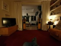
Never really posted anything 🙂. but read a lot....thanks to all for the information and thanks to Mr. Pass for the wonderful amplifiers and all his help! This is my build. Sounds great....really great! Hope you like the photos!
Kind regards,
George.
Great to know these boards sound good as I've nearly finished a similar build. I also have the transformers quite close to the boards and was wondering if you tried without the transformer screen can? Did you get noise from the transformer being close to the board?
Happy listening!
Steve
Hello Shteve,
I always use toroids "cans" and always ground them to the chassis (using a bolt) to prevent hum and noise..in my experience no hum or noise is passing through the signal thus gets amplified and annoying if you follow some simple steps.
1)I always use the star grounding method and always works great...if you see on my pictures you can actually see the star grounding between the power supply pcbs.
2)Also important is to shield the input signal which is the most sensitive to pick up noise....i recommend to use shielded cable there...
3)try to keep every metal object in the amplifier (eg an 7805 regulator heat sink) to the ground too....even a tiny thing can pick up noise and statics....and amplify it..
my build is VERY stressed in terms of space...maybe toooo much...but no hum or noise is audible . it is dead silent 🙂
hope this was helpful.
Kind regards,
George.
hopes this helps.
Hi George
Thanks for the suggestions, I'll order the torod cans today.
One other question on your amp - what are the orange blocks mounted half way down the amp board? I presume switches, but what are they switching?
I've thought of trying a 2 stage bias that would have a switch (and pot) in a similar position. One stage would have optimal ~0.3 amp bias for listening, and the other stage a much lower bias for back ground listening, and less heat, like some of the Mood Right amps.
Has anyone else tried this with the F5T? (I plan to get the standard, non bias switched version working first)
Best regards
Steve
These output devices don't sound great at low bias, FWIW. There is already quite low OLG and lowering it further by dropping the bias isn't a fantastic starting point.
It might be more productive to disable a few pairs with your switching system. This way the bias for each individual device set doesn't change, so you still retain some semblance of performance. Each pair (on each channel) will require two contacts to realise the change.
It might be more productive to disable a few pairs with your switching system. This way the bias for each individual device set doesn't change, so you still retain some semblance of performance. Each pair (on each channel) will require two contacts to realise the change.
Hello again Shteve and Sangram,
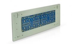
The two orange "blocks" are DPDT relays. i do not play with the biasing. I prefer it to be stable and because i don't use HUGE heat sinks i got it at 0.3volts as suggested by Nelson. The relays are controlling the gain of the amp. i have 2 choices there. The normal gain (think it is about 17db) and a higher gain thus more power of the amp at about 23db. Why ? simply because with higher gain comes more kick and more acoustic power. And some times i need it! 🙂. How is this possible? if you look at the schematic the gain is set by 4 resistors (2 pairs of 2 parallel 220Ohm ones). thus 110ohm a pair since they are in parallel. the relays when triggered simply cut of the one resistor and make the resistance 220ohm ..giving more gain. with gain comes more (maybe even not audible distortion...) that is why i want it switchable. most of the time i use the original gain setup. Why relays and not just a simple switch? well i am a bit crazy with these matters....i dint want the signal to travel with cables inside the case in order to go to the back panel where the switch would be mounted....thus i use 2 relays cutting the resistors right on the pcb's 🙂
hope they don't look tooooo bad 😛
The original F5 (15db gain) has two pair of 100ohm (50ohm), and F5 turbo (23db gain) has two pair of 220ohm (110ohm). The 220ohm setting gives you around 30db gain or something like that. So your gain calculation is way off. Also your feedback is comprimised as you only have half the power capability in the resistors.
The bias is also way to low to keep the amp in class A. To get 50W class A at 8ohm you need 1.8A total. wich relates to 0.45V across the source resistors. As it sits, you get 23W class A at 8ohm.
what's your rail voltage? +/-32Vdc or +/-23Vdc?
The bias is also way to low to keep the amp in class A. To get 50W class A at 8ohm you need 1.8A total. wich relates to 0.45V across the source resistors. As it sits, you get 23W class A at 8ohm.
what's your rail voltage? +/-32Vdc or +/-23Vdc?
Last edited:
110/10 is gain of 12. That's not even close to 30dB.
gemenakis, I was talking to Shteve and his requirement of a second bias level 🙂
gemenakis, I was talking to Shteve and his requirement of a second bias level 🙂
it's 220. not 110.
there is 2pc 220ohm in paralell (110ohm). The relay cuts out one of the resistors to get 220ohm.
And at the same time reduces the power handling from 6-10W to 3-5W.
there is 2pc 220ohm in paralell (110ohm). The relay cuts out one of the resistors to get 220ohm.
And at the same time reduces the power handling from 6-10W to 3-5W.
Last edited:
Hello again Shteve and Sangram,
The two orange "blocks" are DPDT relays. i do not play with the biasing. I prefer it to be stable and because i don't use HUGE heat sinks i got it at 0.3volts as suggested by Nelson. The relays are controlling the gain of the amp. i have 2 choices there. The normal gain (think it is about 17db) and a higher gain thus more power of the amp at about 23db. Why ? simply because with higher gain comes more kick and more acoustic power. And some times i need it! 🙂. How is this possible? if you look at the schematic the gain is set by 4 resistors (2 pairs of 2 parallel 220Ohm ones). thus 110ohm a pair since they are in parallel. the relays when triggered simply cut of the one resistor and make the resistance 220ohm ..giving more gain. with gain comes more (maybe even not audible distortion...) that is why i want it switchable. most of the time i use the original gain setup. Why relays and not just a simple switch? well i am a bit crazy with these matters....i dint want the signal to travel with cables inside the case in order to go to the back panel where the switch would be mounted....thus i use 2 relays cutting the resistors right on the pcb's 🙂
hope they don't look tooooo bad 😛
Thanks for the explication George. I like the idea, but think I would need to go the other way and cut gain if I were to implement your version. I have a korgB1 which seems to have way too much gain for my 22dB power amp (L25d - soon to be replaced by F5T) and ~82dB sensitivity speakers, and my listening habits. Maybe I have chosen the wrong project with the F5T, but I'm 5 years in and just got the chassis built and PSU assembled up to cap Bank and the amp board are mainly populated. Relatively speaking, I'm nearly there finished.
The relay cuts out one of the resistors to get 220ohm.
Which schematic is this on?
It's not on any schematic.
"The two orange "blocks" are DPDT relays. i do not play with the biasing. I prefer it to be stable and because i don't use HUGE heat sinks i got it at 0.3volts as suggested by Nelson. The relays are controlling the gain of the amp. i have 2 choices there. The normal gain (think it is about 17db) and a higher gain thus more power of the amp at about 23db. Why ? simply because with higher gain comes more kick and more acoustic power. And some times i need it! . How is this possible? if you look at the schematic the gain is set by 4 resistors (2 pairs of 2 parallel 220Ohm ones). thus 110ohm a pair since they are in parallel. the relays when triggered simply cut of the one resistor and make the resistance 220ohm ."
"The two orange "blocks" are DPDT relays. i do not play with the biasing. I prefer it to be stable and because i don't use HUGE heat sinks i got it at 0.3volts as suggested by Nelson. The relays are controlling the gain of the amp. i have 2 choices there. The normal gain (think it is about 17db) and a higher gain thus more power of the amp at about 23db. Why ? simply because with higher gain comes more kick and more acoustic power. And some times i need it! . How is this possible? if you look at the schematic the gain is set by 4 resistors (2 pairs of 2 parallel 220Ohm ones). thus 110ohm a pair since they are in parallel. the relays when triggered simply cut of the one resistor and make the resistance 220ohm ."
Ah okay I think some wires crossed between the two conversations.
220/10 is 27dB, which is 6dB more than the standard F5T gain. That's also 6dB less feedback which then affects performance directly.
220/10 is 27dB, which is 6dB more than the standard F5T gain. That's also 6dB less feedback which then affects performance directly.
Hello all again 🙂
I love the idea of managing the gain. That is why i did the relays switch. For me it is a must option. Other than that...most of the times as i mentioned the amp is in its original mode. @AudioSan i don't think that the gain is 30db...if not 24 as i mentioned it is 27db with the 220ohm setting. Also the rails are at 34 VDC.about the bias...it is at 300mv because i am worried of thermal issues...the heat sinks as you see in the photos are not something huge...and i need this amp to stay cool and friendly. I am thinking of putting on some very low spinning fans to cool the sinks so then i can also bias the amp higher...at 0.4v maybe! Thanks for your input 🙂.
Sangram thanks also 🙂
Shteve go for it anyway you want! it will be great anyway 🙂. i think your loudspeakers are a bit low on sensitivity though for this amp!
Hi all,
Have some power supply questions (let me know if this is better directed to the universal PSU thread). I am planning on running an Antek 15635 or 10435 (depending on budget) for about ~50v rails on V3 monoblocks. I'm going to couple two power supply boards per monoblock so I can fit 16x 15,000uf caps in each.
1.) What is the recommended pi resistor setup? All 14 resistor slots filled for both boards?
2.) Fill both corresponding rectifier boards (16 diodes total for each PSU)? Is my memory correct in recalling that people just use the MUR3020W in the PSU as well?
3.) No input snubbers but use the specified output snubbers in the PSU BOM, correct? (think I remember reading that at some point, but could be totally wrong)
Thanks for any input / clarifications!
Attachments
Hello all again 🙂
I love the idea of managing the gain. That is why i did the relays switch. For me it is a must option. Other than that...most of the times as i mentioned the amp is in its original mode. @AudioSan i don't think that the gain is 30db...if not 24 as i mentioned it is 27db with the 220ohm setting. Also the rails are at 34 VDC.about the bias...it is at 300mv because i am worried of thermal issues...the heat sinks as you see in the photos are not something huge...and i need this amp to stay cool and friendly. I am thinking of putting on some very low spinning fans to cool the sinks so then i can also bias the amp higher...at 0.4v maybe! Thanks for your input 🙂.
Sangram thanks also 🙂
Shteve go for it anyway you want! it will be great anyway 🙂. i think your loudspeakers are a bit low on sensitivity though for this amp!
The speakers are an old project that do sound supprisingly good, with a sub.
Monitor W15NeoSEAS W15CY001 +
But I've wanted a pair of Martin logan since I heard The Sequel II with a big hot Krell. I promised myself that I would finish the F5T project before changing speakers.
Anyone using the F5T with Martin logan? I was thinking a pair of old Theos would just about fit my space.
Attachments
- Home
- Amplifiers
- Pass Labs
- F5 Turbo Builders Thread