Those are parallel circuits. Just leave open. Refer to the V3 schematic and it should be clear.
Just use the locations you want to use. Leave others empty. Skipping allows for better heat spread.
thanks guys, I'll compare them to the holes in the store chassis heatsinks when I get home. All I need is the transformer and a few parts that will arrive with it to have everything except wire tracked down. I probably have enough, but I want this one all properly color co ordinated! to date, this is the 2nd most expensive build I've done, (First place goes to a 70 watt P-P tube amp of 70 watts) it may take first place by the time I'm done, still reasonable for the caliber of amplifier here. Havent bought a single tube or built a tube anything since I began down the DIY Pass road, that's for sure!
Russellc
Russellc
When you use Teas boards but are only doing V-2 (two pairs per side)
Do you just install the Fets and associated resistors in the positions you want to use, or is there any jumpering involved, like one would do on the cascode positions if one was not using cascode? I asked this also on the Build thread but havent received any feedback, thought this might be more appropriate?
Thanks,
Russellc
Russellc,
In order to make this work, you have to jumper the bipolars to make it look like a V1-V2. See attached.
Attachments
Russellc,
In order to make this work, you have to jumper the bipolars to make it look like a V1-V2. See attached.
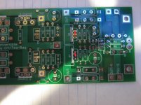
Sorry Tea-bag, I didnt say this, but my V2 WILL be using the cascode, Buzz knew this because I purchased his GB parts kit. But otherwise this is exactly the info I am looking for. Those are some thick boards!
Russellc
Good look with the build Russellc you'll be well pleased with the sound of this amp.
Thickest boards I've seen.
Thickest boards I've seen.
Choices: Mosfet mounting, diode mounting
I've been turning this over and over as to the preferable way, has come down to 2 choices.
Choice 1:
Solder the mosfets to the boards, (Tea-bags boards, not store) and Mount them to heatsink. Advantages: less solder points than choice 2 will present, and lack of flying leads from the boards to the mosfets, which choice 2 will also present. Disadvantages: While I am assured by Buzz (who should certainly know!) that I am OK, problem is the Mosfet pair, remember on Teas boards I'm using the pair is above and below each other while the store board (IIRC) has them side by side, with diodes below each mosfet. The side to side method does not place them on the center, but each mosfet is closer to the outside edge of the sink. But, one is on one side, the other on the other side. With Teas boards, with the mosfet pairs being above and below each other, this positions the pair about 1/3 of the way across the heat sink, (1/2 way point would be center) BUT...since they are above and below each other, all the heat is off center to this one side. If this doesnt matter, I think my choice is clear, #1.
Choice 2:
Mount the mosfet pairs right on the center positions, and run leads (about 2-3 inches tops) from the board locations.
Advantages: Mosfets centered, and coincidentally leaves all 4 diode positions exactly lined up with a predrilled/tapped hole for there mounting to the sink, if one decides to do it that way..I'm not decided on that yet.
Disadvantages: The leads have to be added. Thinking back to the big F-5 thread I remember this being discussed, and I recall all was OK as long as they were less than 12 inches. Seems like I remember (maybe another project) something about if you did this to also move the associated resistor to the mosfet on the end of the lead so it is still in close proximity to the mosfet? I may recall this incorrectly. Similarly, leads would have to be run from the board to the thermistors, so they can be close to the mosfet...
Then I suppose "choice 3" could be, just buy the store boards, which I really dont want to, as I want to use Teas....
Any thought, ideas, criticisms, etc would be greatly appreciated. While I dont intend to bias it to the very edge, I hadnt planned on leaving it at lower bias levels to control heat, so I dont consider this an option. Surely some other person here has worked there way through the dilemma.
Are the off centered and above and below pair going to be OK in this 1/3 position? If questionable, I may opt for choice#2. I also understand that what works for the F-5 may not work for the twitchier Turbo version. Obviously, this is driving me nuts.
Russellc
Last edited:
I would go for choice #1 and bias as high as your sinks allow. I don't think the little extra bias you could run with choice #2 would be of enough benefit to be worth the work. This is just my lazy opinion.
I would go for choice #1 and bias as high as your sinks allow. I don't think the little extra bias you could run with choice #2 would be of enough benefit to be worth the work. This is just my lazy opinion.
Thanks, much appreciated. trust me, the lazy and easier way is very appealing
to me. But, as I will be using this amp for some time, I'd like to do it right. My standard F-5 has rather large M&M heatsinks, and the pair is positioned side by side (Peter Daniels Boads) and seem more massive than the store chassis sinks. They can get fairly warm, but never so bad I cant leave my hand on it. Maybe they are more efficient that they look.
Russellc
Last edited:
Russellc,
Something I have done to a pair of my heatsinks is attach some angle aluminum to them to dissapate heat on the inside. I have also epoxied CPU heatsinks to those as well.
The truth is, this amp will belt out the heat, and eventually you will want to bias lower.
Something I have done to a pair of my heatsinks is attach some angle aluminum to them to dissapate heat on the inside. I have also epoxied CPU heatsinks to those as well.
The truth is, this amp will belt out the heat, and eventually you will want to bias lower.
This is exactly why I am so paranoid about the mosfets position on the sink,but will this help? If so, I would run short leads to the mosfets. If not, and the pair will operate just as well not centered, then I'm not going to worry about it.
As I said earlier, I dont intend on running this amp at maximum bias, but dont want to have to run it at sissy levels just because my fets are not positioned to make maximum use of the sinks cooling ability. I can see that this case can do the job, (V-2) but IS NOT oversized sinkwise. I do understand that every sink has its limits, and at some point that is all the bias it can reasonably be expected to deal with.
I was just a little concerned, and maybe I shouldnt be but it occurs to me that both mosfets of the pair are positioned above and below each other and over to one side. If this really wont make any difference in sinking the pair, then I should just proceed. Maybe its OCD and me wanting it to be symmetrical.... will a sink dissipate just as well with the pair off to one side as described, or would it be more efficient centered? If "centered" will the short leads be a problem?
Russellc
Last edited:
Hi Russ,
Sorry for the off-comment about your menu....
This amp deserves an utmost respect when it comes to heat, thus it also deserves an extra effort. No shortcuts as much as possible.
If this amp will be an experimental build, just go for no 1 and should be no problem. If no 2, we don't know yet what will be the issue you will encounter.
IMHO, I will not take your 2 options, I will add option no 4...which will address both weaknesses of your option 1 and 2. One thing about option 4, it added beauty factor that will add points on your build😎😎.
Regards,
F5T V2 Ground Loop isolation
Hi,
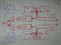
I am near to complete the F5T and I have a question about the ground loop isolation. I attach a sketch (really a "sketch" and I hope is readable) where I show the ground connection only. As you can see is a dual mono that in common have only the 220V power supply.
In the sketch I show in blue the 2 bridge with the 2 thermistor. Is acceptable to connect the loop to the PSU or should be on the star point? Actually I have no more room on the FE. The connection of the negative of the speakers was really complicated.
Thanks and Regards,
Enrico
Hi,
I am near to complete the F5T and I have a question about the ground loop isolation. I attach a sketch (really a "sketch" and I hope is readable) where I show the ground connection only. As you can see is a dual mono that in common have only the 220V power supply.
In the sketch I show in blue the 2 bridge with the 2 thermistor. Is acceptable to connect the loop to the PSU or should be on the star point? Actually I have no more room on the FE. The connection of the negative of the speakers was really complicated.
Thanks and Regards,
Enrico
Attachments
Last edited:
Eme,
that looks right.
You have two separated channels each with their own Main Audio Ground (MAG).
The only connection between these two MAGs is via the two sets of diode bridges to Chassis.
I don't know the FE PCB trace layout, but it's worth checking where the Input Screens should connect to. As far as I am concerned, the input pair of Signal Hot and Signal Screen/Ground must make up a close coupled pair for the whole input circuit.
Thanks Andrew,
I am using the Stor PCB and the Signal HOT is just near the Signal Ground. In the sketch I show only the shield of the signal.
I read on some thread that with my configuration the diode bridge to the chassis should be only one but in this way I have to connect the 1 ground of the 2 PSU. Now I am more confident that I choose the correct way
Cheers
Enrico
If your amplifier has only one MAG then that one MAG requires one connection to Chassis to pass Fault current via Chassis to PE.
If your amplifier has two separate MAGs then each of those MAGs require a connection to Chassis to pass Fault current via Chassis to PE. In in this situation you use one connection to chassis then that results in the two MAGs not being separate.
If your amplifier has two separate MAGs then each of those MAGs require a connection to Chassis to pass Fault current via Chassis to PE. In in this situation you use one connection to chassis then that results in the two MAGs not being separate.
Oh well, since no one has tried it with leads and nobody therefore knows whether it will work, I'm shelving this project. Awful lot of money in it....should have followed my original idea of Aleph 2 monos. Much less of a "Beta" build.
Its hard to imagine everyone who bought the kit and Teas boards that no one has worked through this. I guess everyone who bought Teas boards did not use the store chassis, and built there own, another thing I should have done.
If you are using the same boards I am, and are contemplating the store chassis for V-2, my advice is dont. Build it yourself.
I guess I could retrofit my F-5 into this store chassis, and build V-2 in my F-5 box I built, It has larger heat sinks anyway. Judging on the heat it can generate (not excessive) I dont believe the store chassis is quite big enough if Turbo is that much of a heat monster.
Another option for me is to use the pair of Cviller F-5c 2 pair boards and forget the diodes. This may be the best Idea, I think the F-5c boards are designed on the standard store spacing. I am also getting in on 6L6s aleph J kit, this would be a nice box for it.
Thanks for all the tips and advice everyone, I will have to finish this Turbo F-5 later, if at all.
I'll just keep an eye on other's builds and see how it goes. Now to re-begin collecting Aleph 2 parts!
Russellc
Last edited:
Russell,
PKI has had the F5T on the store 5u chassis. It worked fine, but did get warm. It's Class A, so no worries. The store baords were more ideally created for the chassis, but they have their drawbacks. Do not let this keep you from building it. It will not be a major issue.
PKI has had the F5T on the store 5u chassis. It worked fine, but did get warm. It's Class A, so no worries. The store baords were more ideally created for the chassis, but they have their drawbacks. Do not let this keep you from building it. It will not be a major issue.
Yep. I would say dissipation was not an issue, I even trimmed it up too far and riched the diode conductivity point... and BA-BAM! 🙂
- Home
- Amplifiers
- Pass Labs
- F5 Turbo Builders Thread